9
equipment off and on, the user is encouraged to try to correct the interference by one or more of the
following measures:
-- Reorient or relocate the receiving antenna.
-- Increase the separation between the equipment and receiver.
-- Connect the equipment into an outlet on a circuit different from that to which the receiver is connected.
-- Consult the dealer or an experienced radio/TV technician for help.
RF exposure warning
This equipment must be installed and operated in accordance with provided instructions and the
antenna(s) used for this transmitter must be installed to provide a separation distance of at least 20 cm
from all persons and must not be co-located or operating in conjunction with any other antenna or
transmitter. End-users and installers must be provided with antenna installation instructions and
transmitter operating conditions for satisfying RF exposure compliance.
IEEE 802.11b, 802.11g or 802.11n (20MHz) operation of this product in the U.S.A. is firmware-limited to
channels 1 through 11. IEEE 802.11n (40MHz) operation of this product in the U.S.A. is firmware-limited
to channels 3 through 9.
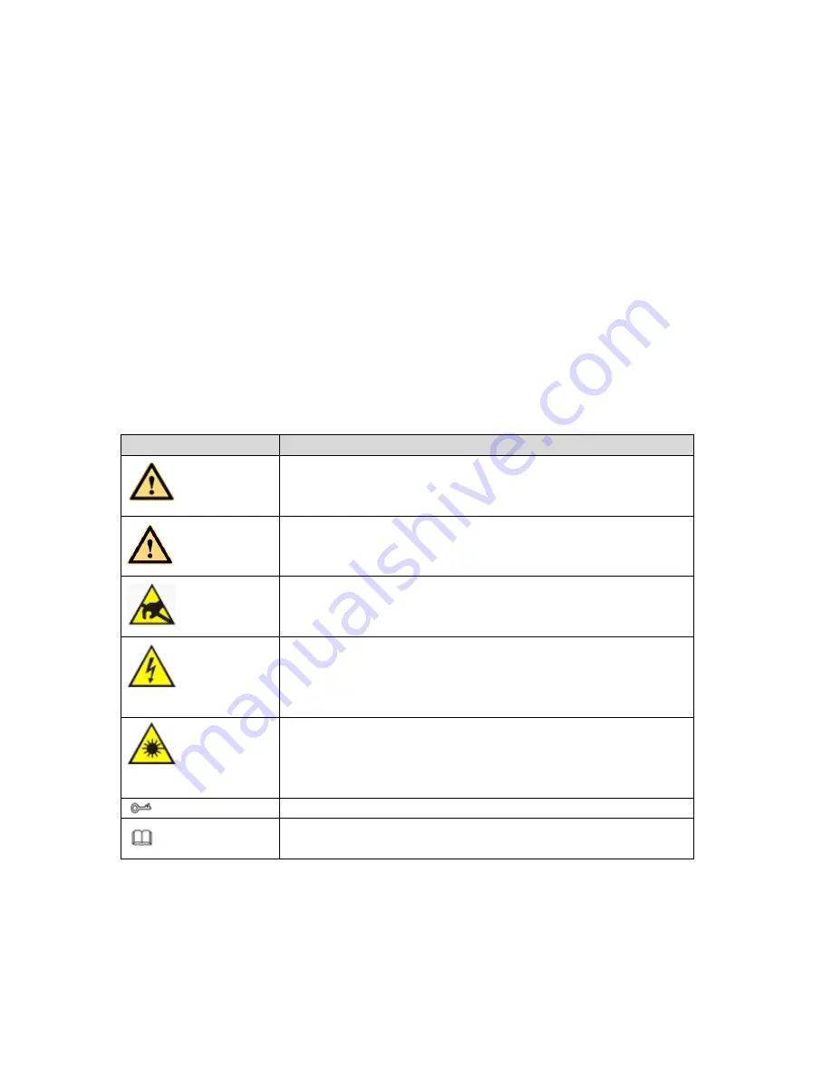
Safety Instruction
Icon
Note
DANGER
Indicates a hazard with a high level of risk, which if not avoided, will
result in death or serious injury.
WARNING
Indicates a potentially hazardous situation, which if not avoided,
could result in device damage, data loss, performance degradation,
or unexpected results.
Anti-static
Indicates it is the static sensitive device.
Eletric shock
risk
Indicates presence of dangerous high voltage. There is a risk of
electric shock to persons.
High
power
laser radiation risk
Indicates presence of high power laser radiation.
Tips
It is intended to help you to fix a problem or save your time.
Note
Provides additional information to emphasize or supplement
important points of the main text.
Summary of Contents for NVR-ELE4ME-WS
Page 33: ...163 Figure 3 3 3 5 4 Compact 1U Series Please refer to Figure 3 4 for connection sample...
Page 51: ...181 Figure 3 24...
Page 63: ...193 Figure 4 14 Figure 4 15 Step 2 Set network camera login password WARNING...
Page 71: ...201 Figure 4 24 Step 2 Click device display edit interface See Figure 4 25...
Page 148: ...278 Figure 4 114 Figure 4 115...
Page 159: ...289 Figure 4 126 Figure 4 127...
Page 161: ...291 Figure 4 129 Click draw button to draw the zone See Figure 4 130...
Page 165: ...295 Figure 4 133 Click Draw button to draw a zone See Figure 4 134 Figure 4 134...
Page 170: ...300 Figure 4 139 Click draw button to draw the zone See Figure 4 140...
Page 183: ...313 Figure 4 151 Figure 4 152...
Page 184: ...314 Figure 4 153 Figure 4 154...
Page 250: ...380 Figure 4 236...
Page 294: ...424 Figure 5 60 Figure 5 61...
Page 295: ...425 Figure 5 62 Figure 5 63...
Page 319: ...449 Figure 5 97 Figure 5 98...
Page 322: ...452 Figure 5 101 Figure 5 102...


