225
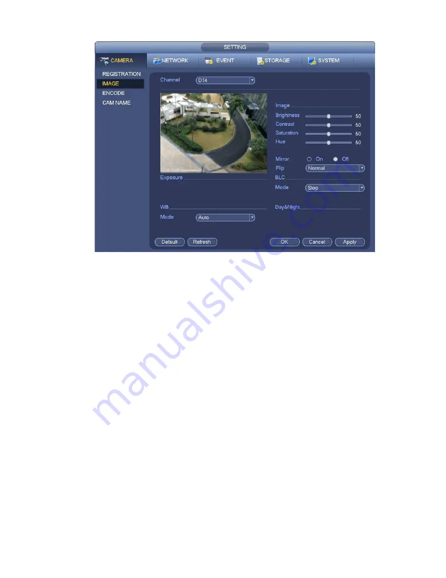
Figure 4-51
4.2.5
Encode
4.2.5.1 Encode
Encode setting is to set IPC encode mode, resolution, bit stream type and etc
From Main menu->Setting->System->Encode, you can see the following interface. See Figure 4-52.
Channel: Select the channel you want.
Type: Please select from the dropdown list. There are three options: regular/motion detect/alarm.
You can set the various encode parameters for different record types.
Compression: System supports H.264, MPEG4, MJPEG and etc.
Resolution: The mainstream resolution type is IPC’s encoding config. Generally there is
D1/720P/1080P. For some series product, the main stream supports 2048
×
1536
(
3M
)
,1920
×
1080
(
1080P
)
, 1280
×
1024
(
S
×
GA
)
, 1280
×
960
(
1.3M
)
,1280
×
720
(
720P
)
,704
×
576
(
D1
)
and
the sub stream supports 704
×
576
(
D1
)
,352
×
288
(
CIF
)
.
Frame rate: It ranges from 1f/s to 25f/s in NTSC mode and 1f/s to 30f/s in PAL mode.
Bit rate type: System supports two types: CBR and VBR. In VBR mode, you can set video quality.
Quality: There are six levels ranging from 1 to 6. The sixth level has the highest image quality.
Video/audio: You can enable or disable the video/audio. Please note, once you enable audio
function for one channel, system may enable audio function of the rest channels by default.
Copy
:
After you complete the setup, you can click Copy button to copy current setup to other
channel(s). You can see an interface is shown as in Figure 4-55. You can see current channel
number is grey. Please check the number to select the channel or you can check the box ALL.
Please click the OK button in Figure 4-55 and Figure 4-53 respectively to complete the setup. Please
note, once you check the All box, you set same encode setup for all channels. Audio/video enable
box, overlay button and the copy button is shield.
Summary of Contents for NVR-ELE4ME-WS
Page 33: ...163 Figure 3 3 3 5 4 Compact 1U Series Please refer to Figure 3 4 for connection sample...
Page 51: ...181 Figure 3 24...
Page 63: ...193 Figure 4 14 Figure 4 15 Step 2 Set network camera login password WARNING...
Page 71: ...201 Figure 4 24 Step 2 Click device display edit interface See Figure 4 25...
Page 148: ...278 Figure 4 114 Figure 4 115...
Page 159: ...289 Figure 4 126 Figure 4 127...
Page 161: ...291 Figure 4 129 Click draw button to draw the zone See Figure 4 130...
Page 165: ...295 Figure 4 133 Click Draw button to draw a zone See Figure 4 134 Figure 4 134...
Page 170: ...300 Figure 4 139 Click draw button to draw the zone See Figure 4 140...
Page 183: ...313 Figure 4 151 Figure 4 152...
Page 184: ...314 Figure 4 153 Figure 4 154...
Page 250: ...380 Figure 4 236...
Page 294: ...424 Figure 5 60 Figure 5 61...
Page 295: ...425 Figure 5 62 Figure 5 63...
Page 319: ...449 Figure 5 97 Figure 5 98...
Page 322: ...452 Figure 5 101 Figure 5 102...


