257
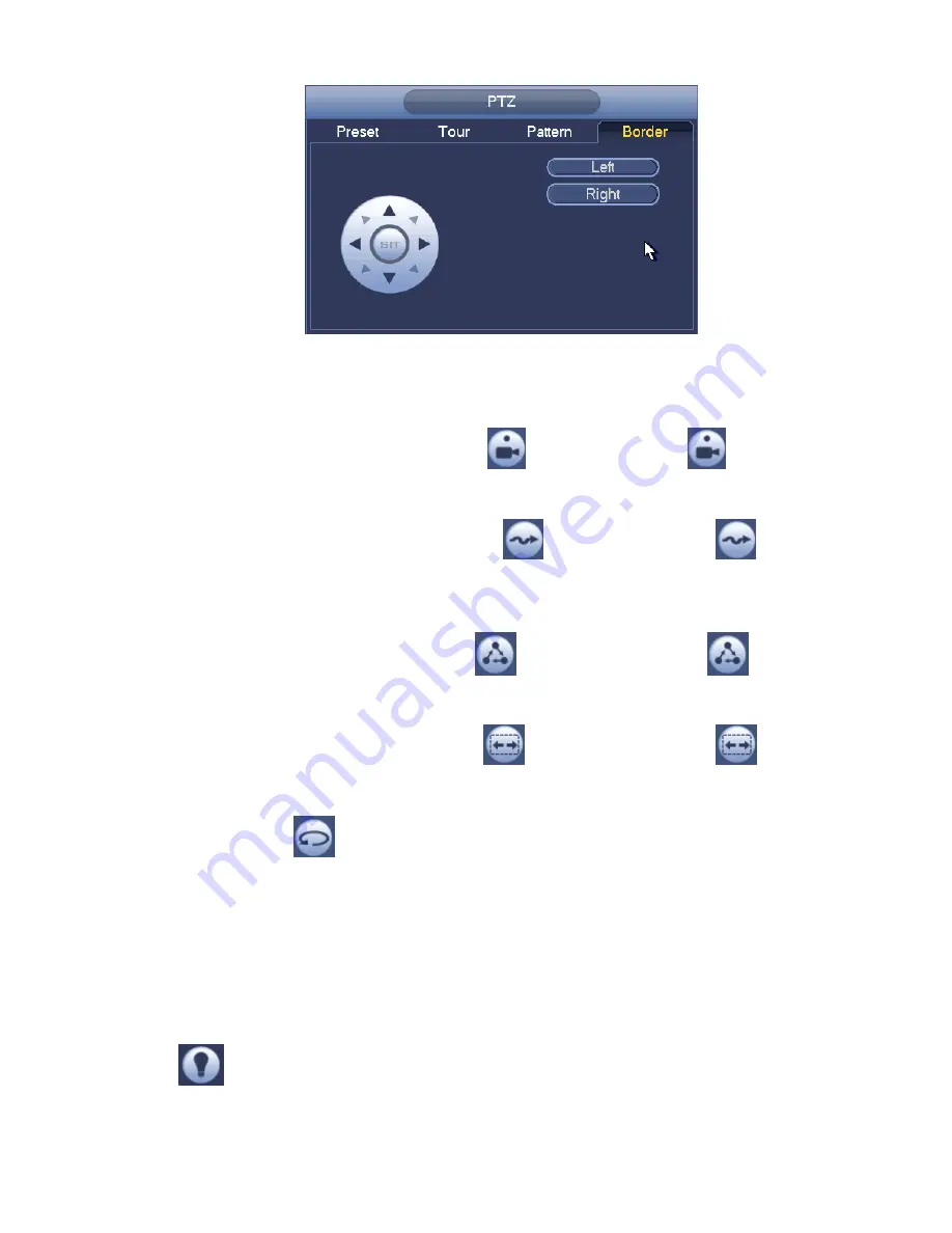
Figure 4-94
4.4.2.2 Call PTZ Function
Call Preset
In Figure 4-89, input preset value and then click
to call a preset. Click
again to stop call.
Call Pattern
In Figure 4-89, input pattern value and then click
to call a pattern. Click
again to stop
call.
Call Tour
In Figure 4-89, input tour value and then click
to call a tour. Click again
to stop call.
Call Scan
In Figure 4-89, input Scan value and then click
to call a tour. Click again
to stop call.
Rotate
In Figure 4-89, click
to enable the camera to rotate.
System supports preset, tour, pattern, scan, rotate, light and etc function.
Note:
Preset, tour and pattern all need the value to be the control parameters. You can define it as yo u
require.
You need to refer to your camera user’s manual for Aux definition. In some cases, it can be used for
special process.
Aux
Click
, system goes to the following interface. The options here are defined by the protocol. The aux
number is corresponding to the aux on-off button of the decoder. See Figure 4-95.
Summary of Contents for NVR-ELE4ME-WS
Page 33: ...163 Figure 3 3 3 5 4 Compact 1U Series Please refer to Figure 3 4 for connection sample...
Page 51: ...181 Figure 3 24...
Page 63: ...193 Figure 4 14 Figure 4 15 Step 2 Set network camera login password WARNING...
Page 71: ...201 Figure 4 24 Step 2 Click device display edit interface See Figure 4 25...
Page 148: ...278 Figure 4 114 Figure 4 115...
Page 159: ...289 Figure 4 126 Figure 4 127...
Page 161: ...291 Figure 4 129 Click draw button to draw the zone See Figure 4 130...
Page 165: ...295 Figure 4 133 Click Draw button to draw a zone See Figure 4 134 Figure 4 134...
Page 170: ...300 Figure 4 139 Click draw button to draw the zone See Figure 4 140...
Page 183: ...313 Figure 4 151 Figure 4 152...
Page 184: ...314 Figure 4 153 Figure 4 154...
Page 250: ...380 Figure 4 236...
Page 294: ...424 Figure 5 60 Figure 5 61...
Page 295: ...425 Figure 5 62 Figure 5 63...
Page 319: ...449 Figure 5 97 Figure 5 98...
Page 322: ...452 Figure 5 101 Figure 5 102...


