SCADA Communications
P746/EN SC/G31
MiCOM P746
(SC) 13-
17
SC
3. MODBUS
INTERFACE
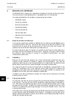
The MODBUS interface is a master/slave protocol and it is defined by MODBUS.org: See
www.modbus.org
MODBUS Serial Protocol Reference Guide: PI-MBUS-300 Rev. E
3.1 Communication
link
This interface also uses the rear EIA(RS)485 port (or converted fiber optic port) for
communication using ‘RTU’ mode communication rather than ‘ASCII’ mode as this provides
more efficient use of the communication bandwidth. This mode of communication is defined
by the MODBUS standard.
In summary, the character framing is 1 start bit, 8 bit data, either 1 parity bit and 1 stop bit, or
two stop bits. This gives 11 bits per character.
The following parameters can be configured for this port using either the front panel interface
or the front Courier port:
−
Baud rate
−
Device address
−
Parity
−
Inactivity time
3.2 MODBUS
functions
The following MODBUS function codes are supported by the relay:
01
Read Coil Status
02
Read Input Status
03
Read Holding Registers
04
Read Input Registers
06
Preset Single Register
08 Diagnostics
11
Fetch Communication Event Counter
12
Fetch Communication Event Log
16
Preset Multiple Registers 127 max
These are interpreted by the MiCOM relay in the following way:
01
Read status of output contacts (0xxxx addresses)
02
Read status of opto inputs
(1xxxx addresses)
03
Read setting values
(4xxxx addresses)
04 Read
measured
values (3xxxx
addresses
06
Write single setting value
(4xxxx addresses)
16
Write multiple setting values
(4xxxx addresses)
Summary of Contents for MiCOM P746
Page 4: ......
Page 5: ...Pxxx EN SS G11 SAFETY SECTION...
Page 6: ......
Page 8: ...Pxxx EN SS G11 Page 2 8 Safety Section BLANK PAGE...
Page 16: ...P746 EN IT G31 Introduction MiCOM P746...
Page 18: ...P746 EN IT G31 Introduction IT 1 2 MiCOM P746 IT BLANK PAGE...
Page 26: ...P746 EN TD G31 Technical Data MiCOM P746...
Page 38: ...P746 EN GS G31 Getting Started MiCOM P746...
Page 78: ...P746 EN ST G31 Getting Started MiCOM P746...
Page 80: ...P746 EN ST G31 Settings ST 4 2 MiCOM P746 ST BLANK PAGE...
Page 112: ...P746 EN ST G31 Settings ST 4 34 MiCOM P746 ST BLANK PAGE...
Page 114: ...P746 EN OP G31 Operation MiCOM P746...
Page 136: ...P746 EN OP G31 Operation OP 5 22 MiCOM P746 OP BLANK PAGE...
Page 138: ...P746 EN AP G31 Application Notes MiCOM P746...
Page 142: ...P746 EN AP G31 Application Notes AP 6 4 MiCOM P746 AP BLANK PAGE...
Page 194: ...P746 EN AP G31 Application Notes AP 6 56 MiCOM P746 AP BLANK PAGE...
Page 196: ...P746 EN PL G31 Programmable Logic MiCOM P746...
Page 238: ...P746 EN MR A11 Measurements and Recording MiCOM P746...
Page 240: ...P746 EN MR A11 Measurements and Recording MR 8 2 MiCOM P746 MR BLANK PAGE...
Page 258: ...P746 EN FD G31 Firmware Design MiCOM P746...
Page 280: ......
Page 348: ...P746 EN MT A11 Maintenance MiCOM P746...
Page 350: ...P746 EN MT A11 Maintenance MT 11 2 MiCOM P746 MT BLANK PAGE...
Page 364: ...P746 EN MT A11 Maintenance MT 11 16 MiCOM P746 MT BLANK PAGE...
Page 366: ...P746 EN TS G31 Troubleshooting MiCOM P746...
Page 368: ...P746 EN TS G31 Troubleshooting TS 12 2 MiCOM P746 TS BLANK PAGE...
Page 382: ...P746 EN SC G31 SCADA Communications MiCOM P746...
Page 424: ...P746 EN SC G31 SCADA Communications SC 13 42 MiCOM P746 SC BLANK PAGE...
Page 426: ...P746 EN SG F21 Symbols and Glossary MiCOM P746...
Page 438: ......
Page 440: ...P746 EN IN G31 Installation IN 15 2 MiCOM P746 IN BLANK PAGE...
Page 468: ......
Page 470: ...P746 EN HI G31 Remote HMI HI 16 2 MiCOM P746 HI BLANK PAGE...
Page 500: ...P746 EN HI G31 Remote HMI HI 16 32 MiCOM P746 HI BLANK PAGE...
Page 502: ......
Page 504: ...P746 EN CS A11G31 Cyber Security CS 17 2 MiCOM P746 CS BLANK PAGE...
Page 524: ...P746 EN VH G31 Firmware and Service Manual Version History MiCOM P746...
Page 529: ......


