Application Notes
P746/EN AP/G31
MiCOM P746
(AP) 6-
49
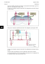
FIGURE 24: BREAKER AND A HALF SCHEME
The above example shows a breaker and a half scheme.
There are 3 feeders connected to each busbar. This configuration requires 1 P746
AP
If it was up to 12 feeders connected to the busbars, the scheme would require 2 sets of 1
P746 or 3 P746.
If it was up to 18 feeders connected to the busbars, the scheme would require 3 P746.
If it was up to 36 feeders connected to the busbars. Each scheme would require 3 P746.
The type of P746 used will depend on the i/o requirements of the scheme in question.
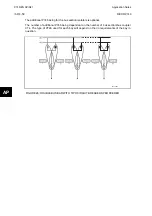
FIGURE 25: DOUBLE BUSBAR APPLICATION WITH BUS COUPLER
The above example shows a double busbar with a bus coupler. It is split into two zones.
If there is a bus coupler with a single CT (solution 1) and up to 5 feeders connected to the
busbar. This configuration requires 1 P746
If there is a bus coupler with CTs on both sides (solution 2) and 4 feeders connected to the
busbar. This configuration requires 1 P746
If there is a bus coupler with a single CT (solution 1) and up to 17 feeders connected to the
busbar. This configuration requires 3 P746
If there is a bus coupler with CTs on both sides (solution 2) and 16 feeders connected to the
busbar. This configuration requires 3 P746
Summary of Contents for MiCOM P746
Page 4: ......
Page 5: ...Pxxx EN SS G11 SAFETY SECTION...
Page 6: ......
Page 8: ...Pxxx EN SS G11 Page 2 8 Safety Section BLANK PAGE...
Page 16: ...P746 EN IT G31 Introduction MiCOM P746...
Page 18: ...P746 EN IT G31 Introduction IT 1 2 MiCOM P746 IT BLANK PAGE...
Page 26: ...P746 EN TD G31 Technical Data MiCOM P746...
Page 38: ...P746 EN GS G31 Getting Started MiCOM P746...
Page 78: ...P746 EN ST G31 Getting Started MiCOM P746...
Page 80: ...P746 EN ST G31 Settings ST 4 2 MiCOM P746 ST BLANK PAGE...
Page 112: ...P746 EN ST G31 Settings ST 4 34 MiCOM P746 ST BLANK PAGE...
Page 114: ...P746 EN OP G31 Operation MiCOM P746...
Page 136: ...P746 EN OP G31 Operation OP 5 22 MiCOM P746 OP BLANK PAGE...
Page 138: ...P746 EN AP G31 Application Notes MiCOM P746...
Page 142: ...P746 EN AP G31 Application Notes AP 6 4 MiCOM P746 AP BLANK PAGE...
Page 194: ...P746 EN AP G31 Application Notes AP 6 56 MiCOM P746 AP BLANK PAGE...
Page 196: ...P746 EN PL G31 Programmable Logic MiCOM P746...
Page 238: ...P746 EN MR A11 Measurements and Recording MiCOM P746...
Page 240: ...P746 EN MR A11 Measurements and Recording MR 8 2 MiCOM P746 MR BLANK PAGE...
Page 258: ...P746 EN FD G31 Firmware Design MiCOM P746...
Page 280: ......
Page 348: ...P746 EN MT A11 Maintenance MiCOM P746...
Page 350: ...P746 EN MT A11 Maintenance MT 11 2 MiCOM P746 MT BLANK PAGE...
Page 364: ...P746 EN MT A11 Maintenance MT 11 16 MiCOM P746 MT BLANK PAGE...
Page 366: ...P746 EN TS G31 Troubleshooting MiCOM P746...
Page 368: ...P746 EN TS G31 Troubleshooting TS 12 2 MiCOM P746 TS BLANK PAGE...
Page 382: ...P746 EN SC G31 SCADA Communications MiCOM P746...
Page 424: ...P746 EN SC G31 SCADA Communications SC 13 42 MiCOM P746 SC BLANK PAGE...
Page 426: ...P746 EN SG F21 Symbols and Glossary MiCOM P746...
Page 438: ......
Page 440: ...P746 EN IN G31 Installation IN 15 2 MiCOM P746 IN BLANK PAGE...
Page 468: ......
Page 470: ...P746 EN HI G31 Remote HMI HI 16 2 MiCOM P746 HI BLANK PAGE...
Page 500: ...P746 EN HI G31 Remote HMI HI 16 32 MiCOM P746 HI BLANK PAGE...
Page 502: ......
Page 504: ...P746 EN CS A11G31 Cyber Security CS 17 2 MiCOM P746 CS BLANK PAGE...
Page 524: ...P746 EN VH G31 Firmware and Service Manual Version History MiCOM P746...
Page 529: ......


