Firmware Design
P746/EN FD/G31
MiCOM P746
(FD) 9-
17
FD
3.4
Protection and control software
The protection and control software task is responsible for processing all of the protection
elements and measurement functions of the relay. To achieve this it has to communicate
with both the system services software and the platform software as well as organize its own
operations. The protection software has the highest priority of any of the software tasks in
the relay in order to provide the fastest possible protection response. The protection &
control software has a supervisor task that controls the start-up of the task and deals with the
exchange of messages between the task and the platform software.
3.4.1
Overview - protection and control scheduling
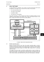
The figure
shows the parts of Schneider Electric software and their allocation on the
different boards.
The P746 relay contained two global protections, busbar protection and circuit breaker
failure, and additional functions such as overcurrent protection.
3.4.2 Topology
processing
Topology algorithm determines dynamically the electric scheme of the substation from the
auxiliary contact of circuit breaker and isolators. At the end of process, the P746 knows the
node of current and zone to trip according to the fault location.
3.4.3 Signal
processing
The sampling function provides filtering of the digital input signals from the opto-isolators and
frequency tracking of the analog signals. The digital inputs are checked against their
previous value over a period of half a cycle.
The frequency tracking of the analog input signals is achieved by a recursive Fourier
algorithm which is applied to one of the input signals, and works by detecting a change in the
measured signal’s phase angle. The calculated value of the frequency is used to modify the
sample rate being used by the input module so as to achieve a constant sample rate of 24
samples per cycle of the power waveform. The value of the frequency is also stored for use
by the protection & control task.
The protection and control calculates the Fourier components for the analogue signals. The
Fourier components are calculated using a one-cycle, 24-sample Discrete Fourier Transform
(DFT). The DFT is always calculated using the last cycle of samples from the 2-cycle buffer,
i.e. the most recent data is used. The DFT used in this way extracts the power frequency
fundamental component from the signal and produces the magnitude and phase angle of the
fundamental in rectangular component format. The DFT provides an accurate measurement
of the fundamental frequency component, and effective filtering of harmonic frequencies and
noise.
This performance is achieved in conjunction with the relay-input module which provides
hardware anti-alias filtering to attenuate frequencies above the half sample rate. The Fourier
components of the input current signals are stored in memory so that they can be accessed
by all of the protection elements’ algorithms. The samples from the input module are also
used in an unprocessed form by the disturbance recorder for waveform recording and to
calculate true rms values of current.
3.4.4
Programmable scheme logic
The purpose of the programmable scheme logic (PSL) is to allow the relay user to configure
an individual protection scheme to suit their own particular application. This is achieved
through the use of programmable logic gates and delay timers.
The input to the PSL is any combination of the status of the digital input signals from the
opto-isolators on the input board, the outputs of the protection elements, e.g. protection
starts and trips, control inputs, function keys and the outputs of the fixed protection scheme
logic. The fixed scheme logic provides the relay’s standard protection schemes. The PSL
itself consists of software logic gates and timers. The logic gates can be programmed to
perform a range of different logic functions and can accept any number of inputs. The timers
are used either to create a programmable delay, and/or to condition the logic outputs, e.g. to
Summary of Contents for MiCOM P746
Page 4: ......
Page 5: ...Pxxx EN SS G11 SAFETY SECTION...
Page 6: ......
Page 8: ...Pxxx EN SS G11 Page 2 8 Safety Section BLANK PAGE...
Page 16: ...P746 EN IT G31 Introduction MiCOM P746...
Page 18: ...P746 EN IT G31 Introduction IT 1 2 MiCOM P746 IT BLANK PAGE...
Page 26: ...P746 EN TD G31 Technical Data MiCOM P746...
Page 38: ...P746 EN GS G31 Getting Started MiCOM P746...
Page 78: ...P746 EN ST G31 Getting Started MiCOM P746...
Page 80: ...P746 EN ST G31 Settings ST 4 2 MiCOM P746 ST BLANK PAGE...
Page 112: ...P746 EN ST G31 Settings ST 4 34 MiCOM P746 ST BLANK PAGE...
Page 114: ...P746 EN OP G31 Operation MiCOM P746...
Page 136: ...P746 EN OP G31 Operation OP 5 22 MiCOM P746 OP BLANK PAGE...
Page 138: ...P746 EN AP G31 Application Notes MiCOM P746...
Page 142: ...P746 EN AP G31 Application Notes AP 6 4 MiCOM P746 AP BLANK PAGE...
Page 194: ...P746 EN AP G31 Application Notes AP 6 56 MiCOM P746 AP BLANK PAGE...
Page 196: ...P746 EN PL G31 Programmable Logic MiCOM P746...
Page 238: ...P746 EN MR A11 Measurements and Recording MiCOM P746...
Page 240: ...P746 EN MR A11 Measurements and Recording MR 8 2 MiCOM P746 MR BLANK PAGE...
Page 258: ...P746 EN FD G31 Firmware Design MiCOM P746...
Page 280: ......
Page 348: ...P746 EN MT A11 Maintenance MiCOM P746...
Page 350: ...P746 EN MT A11 Maintenance MT 11 2 MiCOM P746 MT BLANK PAGE...
Page 364: ...P746 EN MT A11 Maintenance MT 11 16 MiCOM P746 MT BLANK PAGE...
Page 366: ...P746 EN TS G31 Troubleshooting MiCOM P746...
Page 368: ...P746 EN TS G31 Troubleshooting TS 12 2 MiCOM P746 TS BLANK PAGE...
Page 382: ...P746 EN SC G31 SCADA Communications MiCOM P746...
Page 424: ...P746 EN SC G31 SCADA Communications SC 13 42 MiCOM P746 SC BLANK PAGE...
Page 426: ...P746 EN SG F21 Symbols and Glossary MiCOM P746...
Page 438: ......
Page 440: ...P746 EN IN G31 Installation IN 15 2 MiCOM P746 IN BLANK PAGE...
Page 468: ......
Page 470: ...P746 EN HI G31 Remote HMI HI 16 2 MiCOM P746 HI BLANK PAGE...
Page 500: ...P746 EN HI G31 Remote HMI HI 16 32 MiCOM P746 HI BLANK PAGE...
Page 502: ......
Page 504: ...P746 EN CS A11G31 Cyber Security CS 17 2 MiCOM P746 CS BLANK PAGE...
Page 524: ...P746 EN VH G31 Firmware and Service Manual Version History MiCOM P746...
Page 529: ......


