P746/EN OP/G31
Operation
(OP) 5-
18
MiCOM
P746
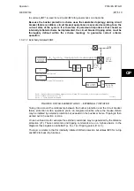
No CB status available directly affects any function within the relay that requires this signal,
for example topology for buscoupler, etc.
If both 52A and 52B are used then status information will be available and in addition a
discrepancy alarm will be possible, according to the following table. 52A and 52B inputs are
assigned to relay opto-isolated inputs via the PSL.
Auxiliary Contact Position
CB State Detected
Action
52A 52B
Open
Closed
Breaker Open
Circuit breaker healthy
Closed
Open
Breaker Closed
Circuit breaker healthy
Closed Closed State
Unknown
Alarm raised if the condition
persists for longer than 150ms
Open Open State
Unknown
Alarm raised if the condition
persists for longer than 150ms
In the bus sections and bus couplers, the position used in the topology algorithm is open
when the ‘CB State Detected’ is ‘Breaker Open’. In all others cases, the position closed will
be used to calculate the topology. CB auxiliary contacts and CB closed command are
definitely required for all bus-sections and bus-couplers.
OP
They are not definitely required for feeders, but if the information is supplied to the scheme,
better operation is possible:
•
Dead Zone fault, the CB position is required (send remote trip order to the other end of
the line).
•
CB supervision.
In that case the best is to provide the Manual CB closing order.
No specific auxiliary contacts are required but ideally one 52a and one 52b should be
available.
The faster these contacts operate (following real CB operation) the better it is.
When 52a=52b=0 or 52a=52b=1 (most of the time during operation of the CB, but not only),
it is recommended that the CB is considered as closed in the topology; this choice is made in
the PSL.
In the PSL:
If 52a is per pole, 52b should be per pole;
If 52a is 3phase, 52b should be 3phase too.
It is recommended to use early make late break contacts for the coupler breaker.
If they do not exist, the CB Close command shall be used to force closed the breaker during
the closing process; this choice is made in the PSL.
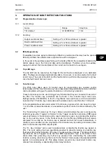
HV CONTACT
AUXILIARY CONTACT a0
AUXILIARY CONTACT b0
AUXILIARY CONTACT ac
AUXILIARY CONTACT bc
CONTACT CLOSED
INTERMEDIATE POSITION
CONTACT OPEN
P0715ENa
Summary of Contents for MiCOM P746
Page 4: ......
Page 5: ...Pxxx EN SS G11 SAFETY SECTION...
Page 6: ......
Page 8: ...Pxxx EN SS G11 Page 2 8 Safety Section BLANK PAGE...
Page 16: ...P746 EN IT G31 Introduction MiCOM P746...
Page 18: ...P746 EN IT G31 Introduction IT 1 2 MiCOM P746 IT BLANK PAGE...
Page 26: ...P746 EN TD G31 Technical Data MiCOM P746...
Page 38: ...P746 EN GS G31 Getting Started MiCOM P746...
Page 78: ...P746 EN ST G31 Getting Started MiCOM P746...
Page 80: ...P746 EN ST G31 Settings ST 4 2 MiCOM P746 ST BLANK PAGE...
Page 112: ...P746 EN ST G31 Settings ST 4 34 MiCOM P746 ST BLANK PAGE...
Page 114: ...P746 EN OP G31 Operation MiCOM P746...
Page 136: ...P746 EN OP G31 Operation OP 5 22 MiCOM P746 OP BLANK PAGE...
Page 138: ...P746 EN AP G31 Application Notes MiCOM P746...
Page 142: ...P746 EN AP G31 Application Notes AP 6 4 MiCOM P746 AP BLANK PAGE...
Page 194: ...P746 EN AP G31 Application Notes AP 6 56 MiCOM P746 AP BLANK PAGE...
Page 196: ...P746 EN PL G31 Programmable Logic MiCOM P746...
Page 238: ...P746 EN MR A11 Measurements and Recording MiCOM P746...
Page 240: ...P746 EN MR A11 Measurements and Recording MR 8 2 MiCOM P746 MR BLANK PAGE...
Page 258: ...P746 EN FD G31 Firmware Design MiCOM P746...
Page 280: ......
Page 348: ...P746 EN MT A11 Maintenance MiCOM P746...
Page 350: ...P746 EN MT A11 Maintenance MT 11 2 MiCOM P746 MT BLANK PAGE...
Page 364: ...P746 EN MT A11 Maintenance MT 11 16 MiCOM P746 MT BLANK PAGE...
Page 366: ...P746 EN TS G31 Troubleshooting MiCOM P746...
Page 368: ...P746 EN TS G31 Troubleshooting TS 12 2 MiCOM P746 TS BLANK PAGE...
Page 382: ...P746 EN SC G31 SCADA Communications MiCOM P746...
Page 424: ...P746 EN SC G31 SCADA Communications SC 13 42 MiCOM P746 SC BLANK PAGE...
Page 426: ...P746 EN SG F21 Symbols and Glossary MiCOM P746...
Page 438: ......
Page 440: ...P746 EN IN G31 Installation IN 15 2 MiCOM P746 IN BLANK PAGE...
Page 468: ......
Page 470: ...P746 EN HI G31 Remote HMI HI 16 2 MiCOM P746 HI BLANK PAGE...
Page 500: ...P746 EN HI G31 Remote HMI HI 16 32 MiCOM P746 HI BLANK PAGE...
Page 502: ......
Page 504: ...P746 EN CS A11G31 Cyber Security CS 17 2 MiCOM P746 CS BLANK PAGE...
Page 524: ...P746 EN VH G31 Firmware and Service Manual Version History MiCOM P746...
Page 529: ......


