P746/EN SC/G31
SCADA Communications
(SC) 13-
14
MiCOM
P746
SC
2.4 Setting
changes
(See R6512, Courier User Guide - Chapter 9)
There are three categories of settings within the relay database:
−
Control and support
−
Disturbance recorder
−
Protection settings group
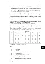
Setting changes made to the control and support settings are implemented immediately and
stored in non-volatile memory. Changes made to either the disturbance recorder settings or
the protection settings groups are stored in a ‘scratchpad’ memory and are not immediately
implemented by the relay.
To action setting changes stored in the scratchpad the save changes cell in the configuration
column must be written to. This allows the changes to either be confirmed and stored in non-
volatile memory, or the setting changes to be aborted.
2.4.1
Setting transfer mode
If it is necessary to transfer all of the relay settings to or from the relay a cell within the
communication system data column can be used. This cell (location BF03) when set to 1
makes all of the relay settings visible. Any setting changes made, with the relay set in this
mode, are stored in scratchpad memory (including control and support settings). When the
value of BF03 is set back to 0 any setting changes are verified and stored in non-volatile
memory.
2.5 Event
extraction
Events can be extracted either automatically (rear port only) or manually (either Courier
port). For automatic extraction all events are extracted in sequential order using the standard
Courier event mechanism, this includes fault/maintenance data if appropriate. The manual
approach allows the user to select events, faults, or maintenance data at random from the
stored records.
2.5.1
Automatic event extraction
(See Chapter 7 Courier User Guide, publication R6512)
This method is intended for continuous extraction of event and fault information as it is
produced. It is only supported via the rear Courier port.
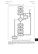
When new event information is created the event bit is set within the status byte, this
indicates to the master device that event information is available. The oldest, unextracted
event can be extracted from the relay using the send event command. The relay will respond
with the event data, which will be either a Courier Type 0 or Type 3 event. The Type 3 event
is used for fault records and maintenance records.
Once an event has been extracted from the relay, the accept event can be used to confirm
that the event has been successfully extracted. If all events have been extracted then the
event bit will reset, if there are more events still to be extracted the next event can be
accessed using the send event command as before.
Summary of Contents for MiCOM P746
Page 4: ......
Page 5: ...Pxxx EN SS G11 SAFETY SECTION...
Page 6: ......
Page 8: ...Pxxx EN SS G11 Page 2 8 Safety Section BLANK PAGE...
Page 16: ...P746 EN IT G31 Introduction MiCOM P746...
Page 18: ...P746 EN IT G31 Introduction IT 1 2 MiCOM P746 IT BLANK PAGE...
Page 26: ...P746 EN TD G31 Technical Data MiCOM P746...
Page 38: ...P746 EN GS G31 Getting Started MiCOM P746...
Page 78: ...P746 EN ST G31 Getting Started MiCOM P746...
Page 80: ...P746 EN ST G31 Settings ST 4 2 MiCOM P746 ST BLANK PAGE...
Page 112: ...P746 EN ST G31 Settings ST 4 34 MiCOM P746 ST BLANK PAGE...
Page 114: ...P746 EN OP G31 Operation MiCOM P746...
Page 136: ...P746 EN OP G31 Operation OP 5 22 MiCOM P746 OP BLANK PAGE...
Page 138: ...P746 EN AP G31 Application Notes MiCOM P746...
Page 142: ...P746 EN AP G31 Application Notes AP 6 4 MiCOM P746 AP BLANK PAGE...
Page 194: ...P746 EN AP G31 Application Notes AP 6 56 MiCOM P746 AP BLANK PAGE...
Page 196: ...P746 EN PL G31 Programmable Logic MiCOM P746...
Page 238: ...P746 EN MR A11 Measurements and Recording MiCOM P746...
Page 240: ...P746 EN MR A11 Measurements and Recording MR 8 2 MiCOM P746 MR BLANK PAGE...
Page 258: ...P746 EN FD G31 Firmware Design MiCOM P746...
Page 280: ......
Page 348: ...P746 EN MT A11 Maintenance MiCOM P746...
Page 350: ...P746 EN MT A11 Maintenance MT 11 2 MiCOM P746 MT BLANK PAGE...
Page 364: ...P746 EN MT A11 Maintenance MT 11 16 MiCOM P746 MT BLANK PAGE...
Page 366: ...P746 EN TS G31 Troubleshooting MiCOM P746...
Page 368: ...P746 EN TS G31 Troubleshooting TS 12 2 MiCOM P746 TS BLANK PAGE...
Page 382: ...P746 EN SC G31 SCADA Communications MiCOM P746...
Page 424: ...P746 EN SC G31 SCADA Communications SC 13 42 MiCOM P746 SC BLANK PAGE...
Page 426: ...P746 EN SG F21 Symbols and Glossary MiCOM P746...
Page 438: ......
Page 440: ...P746 EN IN G31 Installation IN 15 2 MiCOM P746 IN BLANK PAGE...
Page 468: ......
Page 470: ...P746 EN HI G31 Remote HMI HI 16 2 MiCOM P746 HI BLANK PAGE...
Page 500: ...P746 EN HI G31 Remote HMI HI 16 32 MiCOM P746 HI BLANK PAGE...
Page 502: ......
Page 504: ...P746 EN CS A11G31 Cyber Security CS 17 2 MiCOM P746 CS BLANK PAGE...
Page 524: ...P746 EN VH G31 Firmware and Service Manual Version History MiCOM P746...
Page 529: ......


