P746/EN FD/G31
Firmware Design
(FD) 9-
16
MiCOM
P746
FD
3.2
System services software
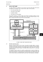
As shown in Figure 8, the system services software provides the interface between the
relay’s hardware and the higher-level functionality of the platform software and the protection
& control software. For example, the system services software provides drivers for items
such as the LCD display, the keypad and the remote communication ports, and controls the
boot of the processor and downloading of the processor code into SRAM from flash EPROM
at power up.
3.3 Platform
software
The platform software has three main functions:
•
To control the logging of records that are generated by the protection software, including
alarms and event, fault, and maintenance records.
•
To store and maintain a database of all of the relay’s settings in non-volatile memory.
•
To provide the internal interface between the settings database and each of the relay’s
user interfaces, i.e. the front panel interface and the front and rear communication ports,
using whichever communication protocol has been specified (Courier or IEC 60870-5-
103).
3.3.1 Record
logging
The logging function is provided to store all alarms, events, faults and maintenance records.
The records for all of these incidents are logged in battery backed-up SRAM in order to
provide a non-volatile log of what has happened. The relay maintains four logs: one each for
up to 32 alarms, 512 event records, 5 fault records and 5 maintenance records. The logs are
maintained such that the oldest record is overwritten with the newest record. The logging
function can be initiated from the protection software or the platform software is responsible
for logging of a maintenance record in the event of a relay failure. This includes errors that
have been detected by the platform software itself or error that are detected by either the
system services or the protection software function. See also the section on supervision and
diagnostics later in this document (P746/EN FD).
3.3.2 Settings
database
The settings database contains all of the settings and data for the relay, including the
protection, disturbance recorder and control & support settings. The settings are maintained
in non-volatile memory. The platform software’s management of the settings database
includes the responsibility of ensuring that only one user interface modifies the settings of
the database at any one time. This feature is employed to avoid conflict between different
parts of the software during a setting change. For changes to protection settings and
disturbance recorder settings, the platform software operates a ‘scratchpad’ in SRAM
memory. This allows a number of setting changes to be applied to the protection elements,
disturbance recorder and saved in the database in non-volatile memory. (See also the
Introduction to this manual (P746/EN IT) on the user interface). If a setting change affects
the protection & control task, the database advises it of the new values.
3.3.3 Database
interface
The other function of the platform software is to implement the relay’s internal interface
between the database and each of the relay’s user interfaces. The database of settings and
measurements must be accessible from all of the relay’s user interfaces to allow read and
modify operations. The platform software presents the data in the appropriate format for
each user interface.
Summary of Contents for MiCOM P746
Page 4: ......
Page 5: ...Pxxx EN SS G11 SAFETY SECTION...
Page 6: ......
Page 8: ...Pxxx EN SS G11 Page 2 8 Safety Section BLANK PAGE...
Page 16: ...P746 EN IT G31 Introduction MiCOM P746...
Page 18: ...P746 EN IT G31 Introduction IT 1 2 MiCOM P746 IT BLANK PAGE...
Page 26: ...P746 EN TD G31 Technical Data MiCOM P746...
Page 38: ...P746 EN GS G31 Getting Started MiCOM P746...
Page 78: ...P746 EN ST G31 Getting Started MiCOM P746...
Page 80: ...P746 EN ST G31 Settings ST 4 2 MiCOM P746 ST BLANK PAGE...
Page 112: ...P746 EN ST G31 Settings ST 4 34 MiCOM P746 ST BLANK PAGE...
Page 114: ...P746 EN OP G31 Operation MiCOM P746...
Page 136: ...P746 EN OP G31 Operation OP 5 22 MiCOM P746 OP BLANK PAGE...
Page 138: ...P746 EN AP G31 Application Notes MiCOM P746...
Page 142: ...P746 EN AP G31 Application Notes AP 6 4 MiCOM P746 AP BLANK PAGE...
Page 194: ...P746 EN AP G31 Application Notes AP 6 56 MiCOM P746 AP BLANK PAGE...
Page 196: ...P746 EN PL G31 Programmable Logic MiCOM P746...
Page 238: ...P746 EN MR A11 Measurements and Recording MiCOM P746...
Page 240: ...P746 EN MR A11 Measurements and Recording MR 8 2 MiCOM P746 MR BLANK PAGE...
Page 258: ...P746 EN FD G31 Firmware Design MiCOM P746...
Page 280: ......
Page 348: ...P746 EN MT A11 Maintenance MiCOM P746...
Page 350: ...P746 EN MT A11 Maintenance MT 11 2 MiCOM P746 MT BLANK PAGE...
Page 364: ...P746 EN MT A11 Maintenance MT 11 16 MiCOM P746 MT BLANK PAGE...
Page 366: ...P746 EN TS G31 Troubleshooting MiCOM P746...
Page 368: ...P746 EN TS G31 Troubleshooting TS 12 2 MiCOM P746 TS BLANK PAGE...
Page 382: ...P746 EN SC G31 SCADA Communications MiCOM P746...
Page 424: ...P746 EN SC G31 SCADA Communications SC 13 42 MiCOM P746 SC BLANK PAGE...
Page 426: ...P746 EN SG F21 Symbols and Glossary MiCOM P746...
Page 438: ......
Page 440: ...P746 EN IN G31 Installation IN 15 2 MiCOM P746 IN BLANK PAGE...
Page 468: ......
Page 470: ...P746 EN HI G31 Remote HMI HI 16 2 MiCOM P746 HI BLANK PAGE...
Page 500: ...P746 EN HI G31 Remote HMI HI 16 32 MiCOM P746 HI BLANK PAGE...
Page 502: ......
Page 504: ...P746 EN CS A11G31 Cyber Security CS 17 2 MiCOM P746 CS BLANK PAGE...
Page 524: ...P746 EN VH G31 Firmware and Service Manual Version History MiCOM P746...
Page 529: ......


