3.
WIRING
IMR01N12-E7
19
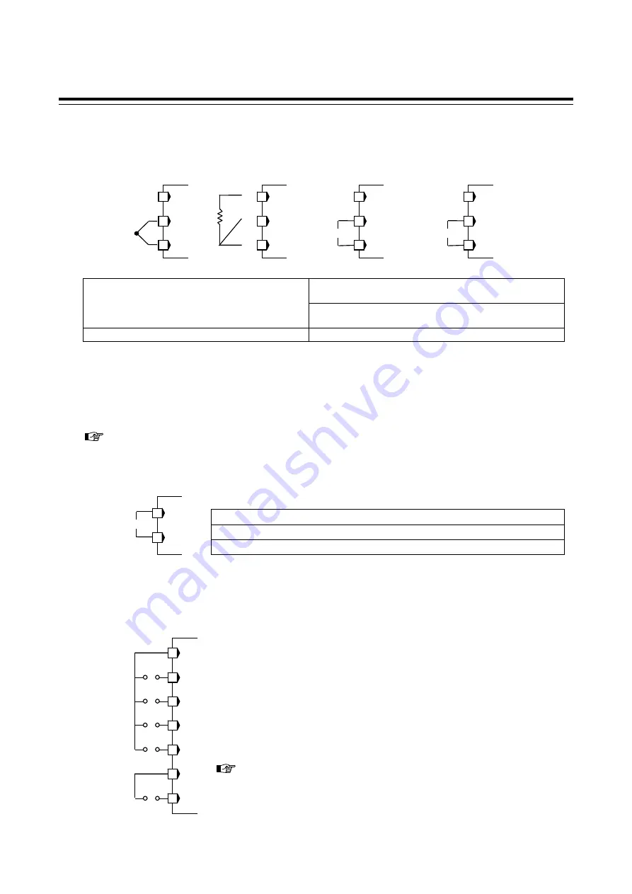
Input 2 (thermocouple, RTD, voltage, and current inputs)
Input 2 can be used for the thermocouple, RTD, voltage, or current input.
For the Input 2, terminals 19 to 21 are allocated to the measured input.
The input types needs to be specified when ordering. The input types are as follows.
Thermocouple: K, J, T, S, R, E, B, PLII, N,
W5Re/W26Re
Voltage (low):
0 to 100 mV DC, 0 to 10 mV DC, 0 to 1 V DC,
10 mV DC,
100 mV DC
Voltage
(high):
0 to 5 V DC, 1 to 5 V DC, 0 to 10 V DC,
1 V DC,
5 V DC,
10 V DC
RTD:
Pt100, JPt100
Current:
0 to 20 mA DC, 4 to 20 mA DC
For thermocouple input, use an appropriate compensation wire. For RTD input, use the same low resistance
lead wires for all connections.
Signal connected to Voltage input and Current input shall be low voltage defined as “SELV” circuit per
IEC 60950-1.
If Input 2 is for voltage input or current input and the sensor power supply is specified to OUT3, terminal
numbers 20 and 21 can be used as sensor signal input terminals for the pressure sensor (with amplifier).
Refer to
Sensor power supply (P. 20)
Remote input (optional)
With non-isolated remote input, terminals 19 to 20 are allocated to Remote input.
Any one of the following input types can be selected.
Voltage (low):
0 to 100 mV DC, 0 to 10 mV DC, 0 to 1 V DC,
10 mV DC,
100 mV DC
Voltage (high):
0 to 5 V DC, 1 to 5 V DC, 0 to 10 V DC,
1 V DC,
5 V DC,
10 V DC
Current:
0 to 20 mA DC, 4 to 20 mA DC
Measured input is not isolated from Remote input (non-isolated type).
Event input (optional)
With Event input, terminals 30 to 36 are allocated to Event input. Event input must be specified when ordering.
Contact input from external devices or equipment should be dry contact input.
If it is not dry contact input, the input should have meet the specifications
below.
Contact specifications:
At OFF (contact open): 500 k
or more
At ON (contact closed) 10
or less
The following functions can be assigned to event inputs.
Memory area selection, RUN/STOP transfer, Remote/Local transfer, Auto/Manual transfer,
Hold reset, Interlock release, Manual output up/down (Motor RPM up/down),
Manual output 0 % reset (Motor RPM reset)
To assign functions to event inputs, refer to
8. ENGINEERING MODE.
(P. 50)
When CC-Link function is specified for Communication function, terminal
Nos.30 to 36 are not available for Event input.
20
19
RS
Thermocouple
Voltage input
Current input
RTD input
20
19
21
TC2
RTD2
A
B
B
20
19
21
20
19
21
IN2
20
19
21
IN2
Dry contact input
DI1
31
30
32
33
35
34
36
DI2
DI3
DI4
DI5
COM
COM


