57
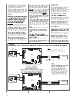
For troubleshooting purposes, follow the
wiring diagram and troubleshooting flow-
chart supplied in this manual and on the
inside of the furnace blower door.
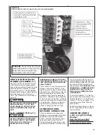
Additionally, the pin designations for the
connector are specified below:
Pin 1 to Inducer High Speed Output.
Pin 2 to Inducer Low Speed Output
Pin 3 is not used.
Pin 4 to Neutral.
NEUTRAL TERMINALS
These terminals connect 115VAC neu-
tral to the furnace control from the input
at the junction box of the furnace.
Additionally, spare terminals are provid-
ed for use with electronic air cleaners,
humidifiers and other accessories as
needed (Check the voltage rating of
your equipment.)
ELECTRONIC AIR CLEAN-
ER (E.A.C.) OUTPUT (J8)
This output is used to energize an elec-
tronic air cleaner. The output will pro-
vide 1.0 amp at 115 VAC. This output is
energized any time the blower motor is
above 40% of maximum airflow capaci-
ty. Airflow below this value is not con-
sidered to be enough for a typical elec-
tronic air cleaner to perform properly.
For 1/2HP motors – Electronic air clean-
er is energized any time the blower is
above 480 CFM (1200 CFM x 0.4)
For 1 HP motors - Electronic air cleaner
is energized any time the blower is
above 800 CFM (2000 CFM x 0.4)
HUMIDIFIER OUTPUT (J8)
These outputs (two) are connected to
the contacts of a control-mounted relay.
In this sense, they are what are called
“dry” contacts. That is, they provide no
voltage, they are only used to close a
circuit. The contacts can be used to
close either a 24VAC or 115VAC circuit
either with a maximum of 1 amp
current.
Details about the humidifier outputs and
wiring diagrams can be found in the
section titled
HUMIDIFICATION AND
DEHUMIDIFICATION of this document.
STEPPER GAS VALVE
CONTROL (J16)
For furnaces equipped with a stepper
modulating gas valve, a five-pin con-
nector is used to control and sense the
gas valve. The valve uses a PWM
(Pulse Width Modulated) signal to con-
trol the firing rate. The duty cycle of
this signal is five percent less than the
expected firing rate. For example, if
the firing rate is 90%, the PWM to (and
from) the valve will be 85% duty cycle.
The connector also provides the
24VAC signal to energize the main
valve solenoid. Reference the wiring
diagram for the furnace printed in this
document or on the inside of the fur-
nace blower door.
For troubleshooting purposes, follow
the wiring diagram and troubleshooting
flowchart supplied in this manual and
on the inside of the furnace blower
door. Additionally, the pin designations
for the connector are specified below:
Pin 1 to stepper modulating gas valve
connector Pin 1 (TH)
Pin 2 to stepper modulating gas valve
connector Pin 2 (RX)
Pin 3 to stepper modulating gas valve
connector Pin 3 (TX)
Pin 4 to stepper modulating gas valve
connector Pin 4 (COMMON)
Pin 5 to stepper modulating gas valve
connector Pin 5 (MVTH)
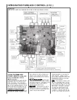
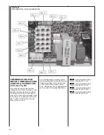
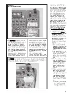
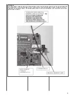
15-PIN MATE-N-LOK CON-
NECTOR (J1) (see Fig 58)
The 15-pin Mate-n-Lok style connector
provides connections for a variety of
inputs and outputs to the furnace con-
trol. For modulating furnaces with a
solenoid-controlled modulating gas
valve (HG or HH Fuel Codes) the 15-
pin connector provides power and con-
trol signals to the gas valve. Also, the
flame sense, pressure switches sense
and limits sense (Main Limit, MRLC
and HALC) are connected to the I.F.C.
through this connector. Reference the
wiring diagram for the furnace printed
in this document or on the inside of the
furnace blower door for pin assign-
ments for troubleshooting.
For troubleshooting purposes, follow
the wiring diagram and troubleshoot-
ing flowchart supplied in this manual
and on the inside of the furnace
blower door. Additionally, the pin
designations for the connector are
specified below:
Pin 1 to Flame Sense rod.
Pin 2 to Overtemp Limit (MRLC)
Sense
Pin 3 to Main Limit (LC) Sense
Pin 4 to 24 VAC to Limit Sense
Circuits
Pin 5
24 VAC out to Auxiliary Limit
(HALC- Heat Assisted Limit
Control)
Pin 6 Solenoid-controlled modulat-
ing gas valve main solenoid
24VAC (not used on fur-
naces with stepper (servo)
modulating gas valve).
Pin 7 is not used on the production
control.
Pin 8 to Low Pressure Switch
sense.
Pin 9 to High Pressure Switch
sense.
Pin 10 to Low and High Pressure
Switch 24VAC
Pin 11
to Aux Input sense
Pin 12 to Ground on furnace cabi-
net
Pin 13 Solenoid-controlled modulat-
ing gas valve control circuit
(not used on furnaces with
stepper (servo) modulating
gas valve).
Pin 14 Solenoid-controlled modulat-
ing gas valve control circuit
(not used on furnaces with
stepper (servo) modulating
gas valve).
Pin 15 Solenoid-controlled modulat-
ing gas valve main solenoid
24VAC common (not used
on furnaces with stepper
(servo) modulating gas
valve).
Summary of Contents for RGFE
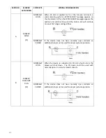
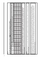
Page 92: ...92 TABLE 21 FURNACE FAULT CODES EXPANDED W DESCRIPTIONS AND SOLUTIONS CONTINUED ...
Page 93: ...93 TABLE 21 FURNACE FAULT CODES EXPANDED W DESCRIPTIONS AND SOLUTIONS CONTINUED ...
Page 94: ...94 TABLE 21 FURNACE FAULT CODES EXPANDED W DESCRIPTIONS AND SOLUTIONS CONTINUED ...
Page 95: ...95 TABLE 21 FURNACE FAULT CODES EXPANDED W DESCRIPTIONS AND SOLUTIONS CONTINUED ...
Page 96: ...96 TABLE 21 FURNACE FAULT CODES EXPANDED W DESCRIPTIONS AND SOLUTIONS CONTINUED ...
Page 97: ...97 TABLE 21 FURNACE FAULT CODES EXPANDED W DESCRIPTIONS AND SOLUTIONS CONTINUED ...
Page 98: ...98 TABLE 21 FURNACE FAULT CODES EXPANDED W DESCRIPTIONS AND SOLUTIONS CONTINUED ...
Page 99: ...99 TABLE 21 FURNACE FAULT CODES EXPANDED W DESCRIPTIONS AND SOLUTIONS CONTINUED ...
Page 102: ...102 TABLE 21 FURNACE FAULT CODES EXPANDED W DESCRIPTIONS AND SOLUTIONS CONTINUED ...
Page 103: ...103 TABLE 21 FURNACE FAULT CODES EXPANDED W DESCRIPTIONS AND SOLUTIONS CONTINUED ...
Page 104: ...104 TABLE 21 FURNACE FAULT CODES EXPANDED W DESCRIPTIONS AND SOLUTIONS CONTINUED ...
Page 105: ...105 TABLE 21 FURNACE FAULT CODES EXPANDED W DESCRIPTIONS AND SOLUTIONS CONTINUED ...

