68
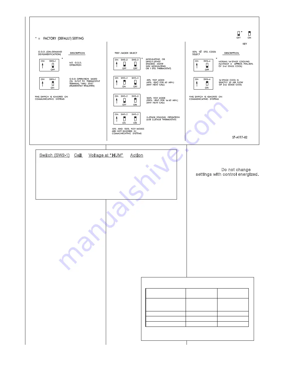
SW2-2 and SW2-3 -
FURNACE TEST and OPERATING
MODES
FURNACE TEST SWITCHES
The Test Switches (SW2) will place the
IFC into a test mode, operating the fur-
nace at continuous input rates of either
100% of full rate (maximum fire) or
40% of full rate (minimum fire). This is
accomplished by setting the Test
Switches as indicated in Table 15
below.
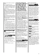
To enter the Furnace Test Mode,
proceed as follows:
1 Switch the 115 volt power to the
furnace OFF. Do not change
settings with control energi
z
ed.
2 Remove furnace blower door.
3 Position Test Switches SW2-2
and SW2-3 for the desired test
mode.
4 Replace furnace blower door.
5. Switch the 115 volt power to the
furnace ON.
6. Set the thermostat mode to
HEAT, adjust the setpoint at least
4°F above room temperature to
demand a call for heating.
When the furnace is powered with
the test switches in a position other
than modulating/single-stage or in 2-
stage mode, the first call for heat
within the first hour after power-up
Switch (SW2-1) Call
Voltage at “ HUM”
Action
ON
COOL
24
Normal Cool (c or C)
ON
COOL
0
Dehum Cool (cd or Cd)
ON
Heat
24
Hum Contacts Closed.
ON
Heat
0
Hum Contacts Open.
OFF
COOL
24
Normal Cool (c or C)
OFF
COOL
0
Normal Cool (c or C)
OFF
Heat
24
Hum Contacts Closed.
OFF
Heat
0
Hum Contacts Open.
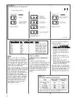
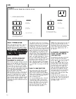
SW2
SW2-1
= ODD “ON” or “OFF” select.
This switch will ignore the input from the
24 volt terminal labeled “HUM STAT”
during cooling when in the “OFF” posi-
tion. However, the “HUM STAT” input is
always read in the heating mode to turn
on and off the humidifier relay.
When in the “ON” position, the dehumid-
ification feature will become active and it
will be necessary to install a humidistat
to the “HUM STAT” terminal as dis-
cussed and shown in wiring diagrams in
the section of this manual titled
“
HUMIDIFICATION AND DEHUMIDIFI-
CATION” of this document. Failure to
install a humidistat to the “HUM STAT”
terminal with dipswitch SW2-1 in the
“ON” position will cause the cooling
speed airflow to be reduced to the
dehumidification speed..
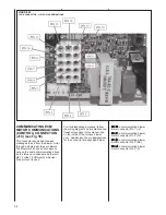
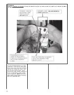
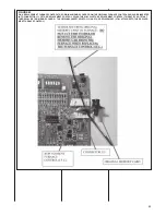
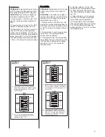
FIGURE 68
DIPSWITCH BANK SW2 TEST MODE SELECT
TABLE 15
SW2-2 AND SW2-3 MODE SELECTION SETTINGS
of full rate (minimum fire and 2-stage operation). This is accomplished by setting
the Test Switches as indicated in Table XX below.
Table XX
- SW2-2 and SW2-3 MODE SELECTION SETTINGS
Mode
Switch SW2-2
Position
Switch SW2-3
Position
Modulating/ Single-
Stage
OFF
OFF
Test 40%
ON
OFF
Test 100%
OFF
ON
Two-Stage
ON
ON
Note: the “
Test 40%
” and “
Test 100%
” settings will time out and become invalid
one hour after power reset.
To enter the Furnace Test Mode, proceed as follows:
1
Switch the 115 volt power to the furnace OFF.
Do not change settings
with control energized.
2
Position Test Switches SW2-2 and SW2-3 for the desired test mode.
3
Switch the 115 volt power to the furnace ON.
4
Set the thermostat mode to HEAT, adjust the setpoint at least 4°F above
room temperature to demand a call for heating.
When the furnace is powered with the test switches in a position other than
modulating/single-stage or in 2-stage mode, the first call for heat within the first
hour after power-up will instruct the furnace to perform as follows:
1
Normal ignition sequence
2
A calibration cycle will be performed unless the Test Switches are set for
Test 40%. The LED status indicator will flash “H” or “h” during the cali-
bration cycle (see Table XX).
NOTE:
The supply air sensor (field installed) is required for the furnace
calibration cycle. If the air sensor is faulty, or not properly connected, the furnace
will not attempt a calibration cycle and will operate on factory default parameters
pre-programmed into the microprocessor.
After calibration, the furnace will then adjust to the desired Test capacity. This
allows time for the technician to check steady-state operation and evaluate
furnace performance.
The furnace will operate at the fixed Test capacity until one of the following
conditions:
A.
The thermostat is satisfied and the call for heat is removed.
B.
The furnace has been in test mode continuously for sixty minutes, at
which time the controller will exit the test mode and proceed to normal
heating operation as configured. Test mode can not be activated again
unless power to the furnace is cycled off and back on. This is true even if
Note: The
“Test 40%”
and
“Test 100%”
settings will time out
and become invalid one hour after power reset.
Summary of Contents for RGFE
Page 92: ...92 TABLE 21 FURNACE FAULT CODES EXPANDED W DESCRIPTIONS AND SOLUTIONS CONTINUED ...
Page 93: ...93 TABLE 21 FURNACE FAULT CODES EXPANDED W DESCRIPTIONS AND SOLUTIONS CONTINUED ...
Page 94: ...94 TABLE 21 FURNACE FAULT CODES EXPANDED W DESCRIPTIONS AND SOLUTIONS CONTINUED ...
Page 95: ...95 TABLE 21 FURNACE FAULT CODES EXPANDED W DESCRIPTIONS AND SOLUTIONS CONTINUED ...
Page 96: ...96 TABLE 21 FURNACE FAULT CODES EXPANDED W DESCRIPTIONS AND SOLUTIONS CONTINUED ...
Page 97: ...97 TABLE 21 FURNACE FAULT CODES EXPANDED W DESCRIPTIONS AND SOLUTIONS CONTINUED ...
Page 98: ...98 TABLE 21 FURNACE FAULT CODES EXPANDED W DESCRIPTIONS AND SOLUTIONS CONTINUED ...
Page 99: ...99 TABLE 21 FURNACE FAULT CODES EXPANDED W DESCRIPTIONS AND SOLUTIONS CONTINUED ...
Page 102: ...102 TABLE 21 FURNACE FAULT CODES EXPANDED W DESCRIPTIONS AND SOLUTIONS CONTINUED ...
Page 103: ...103 TABLE 21 FURNACE FAULT CODES EXPANDED W DESCRIPTIONS AND SOLUTIONS CONTINUED ...
Page 104: ...104 TABLE 21 FURNACE FAULT CODES EXPANDED W DESCRIPTIONS AND SOLUTIONS CONTINUED ...
Page 105: ...105 TABLE 21 FURNACE FAULT CODES EXPANDED W DESCRIPTIONS AND SOLUTIONS CONTINUED ...

