
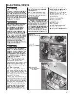
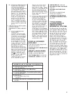

ELECTRICAL CHECKS
Line Power Check
The furnace must have a nominal 115
volt power supply for proper opera-
tion. If there is not a consistent power
supply, contact a licensed electrician
to correct the problem.
1. With the blower compartment door
off, manually hold the push button
door switch in.
2. Call for heat at the thermostat.
3. With the unit operating, use a volt-
meter to measure the voltage from
any 120 VAC terminal to any neu-
tral connection.
4. The voltage should be a nominal
115 volts (acceptable 105-
120VAC).
This test should be made with the unit
in full operation.
Polarity Check
If line & neutral are reversed, a fault
code (26) will be displayed at the fur-
nace seven segment display (SSD)
and at the communicating thermostat
active fault display screen (communi-
cating systems only).
Proper line voltage polarity, or phas-
ing, is a must for this furnace to oper-
ate. Use a volt meter to make this
check.
1. With the blower compartment door
off, manually hold the push button
door switch in.
2. Use a voltmeter to measure the
voltage from any 120 VAC terminal
to any bare metal ground on the
furnace.
3. The voltage should be a nominal
115 volts (acceptable 105-
120VAC).
4. Use a voltmeter to measure the
voltage from any neutral terminal
to the bare metal ground on the
furnace.
5. The voltage should be less than
1.0 VAC.
6. If the voltage from any 120 VAC
terminal to ground is less than 1.0
VAC volts and the voltage from a
neutral to ground is a nominal 115
volts, the polarity is reversed.
7. To correct the problem, either
reverse the hot and neutral wires
to the furnace or have a licensed
electrician check the building
wiring.
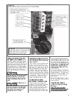
Control Voltage Check
1. With the blower compartment
door off, manually hold the push
button door switch in.
2. Call for heat at the thermostat.
(Does not include communicating
thermostats.)
3. With the unit operating, use a
voltmeter to measure the voltage
from control voltage terminal “W”
46
Summary of Contents for RGFE
Page 92: ...92 TABLE 21 FURNACE FAULT CODES EXPANDED W DESCRIPTIONS AND SOLUTIONS CONTINUED ...
Page 93: ...93 TABLE 21 FURNACE FAULT CODES EXPANDED W DESCRIPTIONS AND SOLUTIONS CONTINUED ...
Page 94: ...94 TABLE 21 FURNACE FAULT CODES EXPANDED W DESCRIPTIONS AND SOLUTIONS CONTINUED ...
Page 95: ...95 TABLE 21 FURNACE FAULT CODES EXPANDED W DESCRIPTIONS AND SOLUTIONS CONTINUED ...
Page 96: ...96 TABLE 21 FURNACE FAULT CODES EXPANDED W DESCRIPTIONS AND SOLUTIONS CONTINUED ...
Page 97: ...97 TABLE 21 FURNACE FAULT CODES EXPANDED W DESCRIPTIONS AND SOLUTIONS CONTINUED ...
Page 98: ...98 TABLE 21 FURNACE FAULT CODES EXPANDED W DESCRIPTIONS AND SOLUTIONS CONTINUED ...
Page 99: ...99 TABLE 21 FURNACE FAULT CODES EXPANDED W DESCRIPTIONS AND SOLUTIONS CONTINUED ...
Page 102: ...102 TABLE 21 FURNACE FAULT CODES EXPANDED W DESCRIPTIONS AND SOLUTIONS CONTINUED ...
Page 103: ...103 TABLE 21 FURNACE FAULT CODES EXPANDED W DESCRIPTIONS AND SOLUTIONS CONTINUED ...
Page 104: ...104 TABLE 21 FURNACE FAULT CODES EXPANDED W DESCRIPTIONS AND SOLUTIONS CONTINUED ...
Page 105: ...105 TABLE 21 FURNACE FAULT CODES EXPANDED W DESCRIPTIONS AND SOLUTIONS CONTINUED ...


