NEUTRALIZER KIT:
RXGY-A01
EXTERNAL BOTTOM FILTER RACK:
RXGF-CB
EXTERNAL SIDE FILTER RACK:
RXGF-CA
These parts are available through
ProStock parts department.
ALTERNATE (LEFT-SIDE) DRAIN
KIT (DOWNFLOW MODELS ONLY):
RXGY-H01
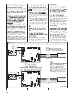
TYPICAL WIRING
ACCESSORIES FOR
COMMUNICATING
RESIDENTIAL SYSTEMS
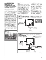
The Rheem Serial Communicating
(CC2) system allows accessories to
be connected to shut down the sys-
tem in the event of a fault. Typical
devices that can be connected are
the drain overflow switch, smoke
detector and freeze protection
switch. There are two methods of
connecting the switch to the system
depending on the device configura-
tion normally closed or normally
open. The blower can run during a
fault or the blower can shut off dur-
ing a fault depending on how the
system is connected. Please refer to
local and/or state codes for installing
these devices. The following opera-
tion applies only when BOTH the
condenser and thermostat are serial
communicating devices. If the con-
denser is non-communicating (tradi-
tional, legacy 24VAC controlled) this
diagram is not valid.
B2. WITH NON-COMMUNICATING
THERMOSTAT (REQUIRES
OPTIONAL HUMIDISTAT).
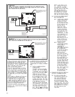
Control of dehumidification only
(no humidification) can be
accomplished by installing an
optional humidistat as shown in
Figure 57 (IV). The dipswitch
SW2-1 must be set to the “ON”
position. If this switch is not
turned “ON”, dehumidification
operation will not take place.
Further, if this switch is “ON”
and no humidistat is installed,
airflow in cooling will be perma-
nently reduced by approximate-
ly 15%.
C. HUMIDIFICATION AND DEHUMIFI-
CATION CONTROL
(REQUIRES OPTIONAL HUMIDIFI-
ER).
C1. WITH COMMUNICATING
THERMOSTAT
Humidifier control is included
with the (-)HC-TST412MDMS
(modulating, non-communicat-
ing) and (-)HC-TST550CMMS
(full-color communicating)
model thermostats. However, it
is not included with the (-)HC-
TST501CMMS model commu-
nicating thermostat. Do not
purchase the latter thermostat if
humidification control is
required. To wire the furnace
for humidification and dehumidi-
fication control using the former
thermostat, refer to the wiring
diagram in Figure 54 (I). Be
sure not
to install the jumper
between “R” and “HUM STAT”
on the furnace control.
Installing this jumper will oper-
ate the humidifier any time
there is a heat call and dehu-
midification will never take
place when in cooling. Without
the jumper, a humidification call
from the thermostat must be
active and a heat call must be
present with the blower running
for the “HUM OUT” relay con-
tacts to close.
C2. WITH NON-COMMUNICATING
THERMOSTAT (REQUIRES
OPTIONAL HUMIDISTAT.)
For non-communicating ther-
mostats, an optional humidistat
must be installed. Controlled
humidification and dehumidifi-
cation can be accomplished
using a humidistat as shown in
Figures 55 (II) or 56 (III).
These figures show installation
of a humidifier with external and
internal power supplies respec-
tively. Dehumidification opera-
tion will be disabled if the dip-
switch SW2-1 is in the “OFF”
position. If this switch is in the
“ON” position, dehumidification
control will be active.
OTHER ACCESSORIES
AVAILABLE
These kits are available through the fin-
ished goods department.
CONCENTRIC VENT TERMINATION KIT
= RXGY-E03A
HORIZONTAL, TWO-PIPE TERMINA-
TION KIT
= RXGY-D02/D02A, RXGY-
D03/D03A, OR RXGY-D04/D04A
VENT TERMINATION KIT:
RXGY-G02
CONDENSATE PUMP KIT:
RXGY-B01
49
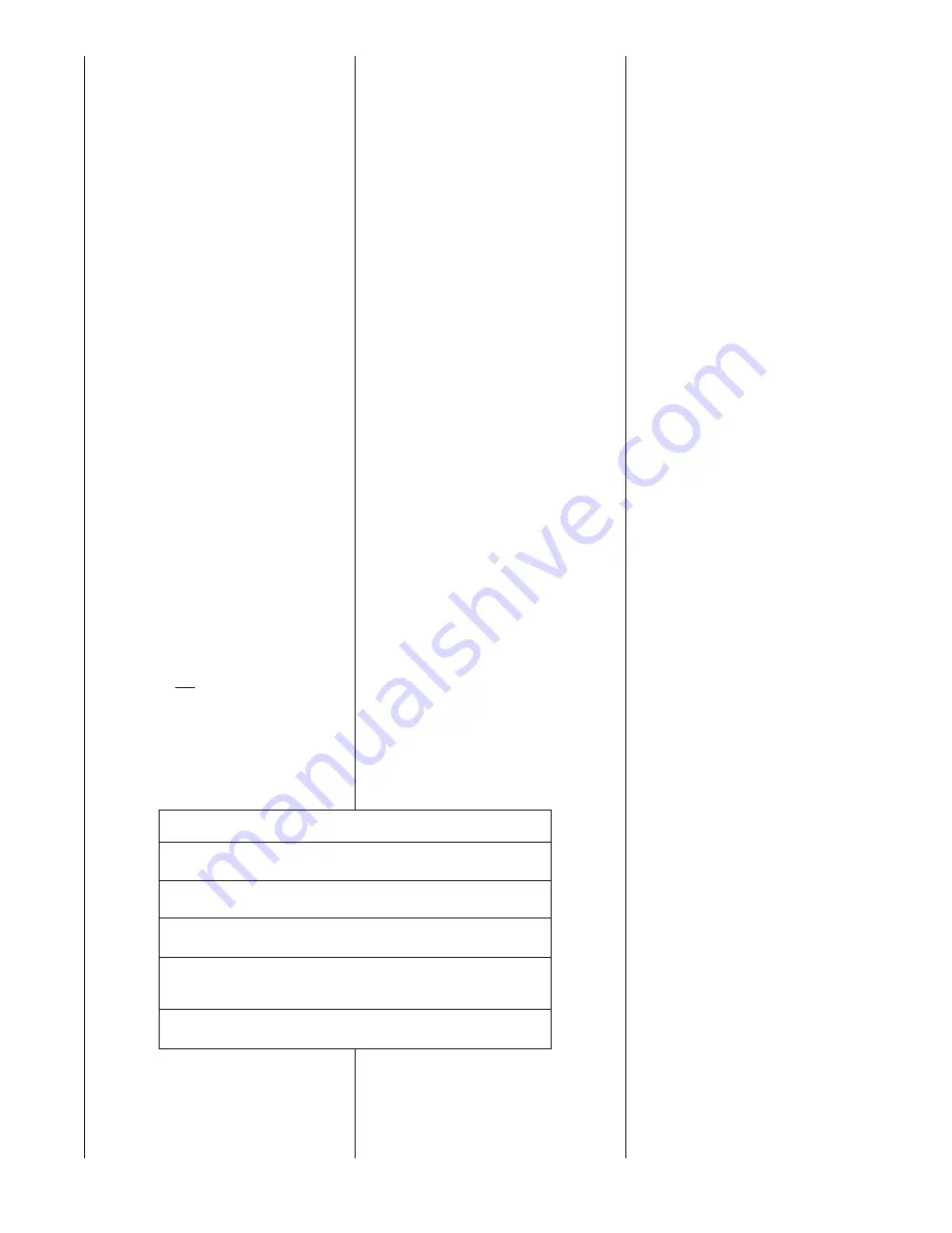
THERMOSTAT AND ACCESSORIES FOR THERMOSTAT
Programmable Modulating Thermostat:
(-)HC-TST412MDMS
Programmable Communicating Modulating:
(-)HC-TST501CMMS
Full-Color, Programmable Communicating Modulating:
(-)HC-TST550CMMS
Remote Sensor:
(For Thermostats Above Only)
F1451378
Thermostat Wall Plate For Thermostats Above Only:
F61-2600
Summary of Contents for RGFE
Page 92: ...92 TABLE 21 FURNACE FAULT CODES EXPANDED W DESCRIPTIONS AND SOLUTIONS CONTINUED ...
Page 93: ...93 TABLE 21 FURNACE FAULT CODES EXPANDED W DESCRIPTIONS AND SOLUTIONS CONTINUED ...
Page 94: ...94 TABLE 21 FURNACE FAULT CODES EXPANDED W DESCRIPTIONS AND SOLUTIONS CONTINUED ...
Page 95: ...95 TABLE 21 FURNACE FAULT CODES EXPANDED W DESCRIPTIONS AND SOLUTIONS CONTINUED ...
Page 96: ...96 TABLE 21 FURNACE FAULT CODES EXPANDED W DESCRIPTIONS AND SOLUTIONS CONTINUED ...
Page 97: ...97 TABLE 21 FURNACE FAULT CODES EXPANDED W DESCRIPTIONS AND SOLUTIONS CONTINUED ...
Page 98: ...98 TABLE 21 FURNACE FAULT CODES EXPANDED W DESCRIPTIONS AND SOLUTIONS CONTINUED ...
Page 99: ...99 TABLE 21 FURNACE FAULT CODES EXPANDED W DESCRIPTIONS AND SOLUTIONS CONTINUED ...
Page 102: ...102 TABLE 21 FURNACE FAULT CODES EXPANDED W DESCRIPTIONS AND SOLUTIONS CONTINUED ...
Page 103: ...103 TABLE 21 FURNACE FAULT CODES EXPANDED W DESCRIPTIONS AND SOLUTIONS CONTINUED ...
Page 104: ...104 TABLE 21 FURNACE FAULT CODES EXPANDED W DESCRIPTIONS AND SOLUTIONS CONTINUED ...
Page 105: ...105 TABLE 21 FURNACE FAULT CODES EXPANDED W DESCRIPTIONS AND SOLUTIONS CONTINUED ...

