52
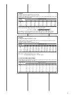
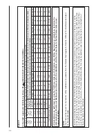
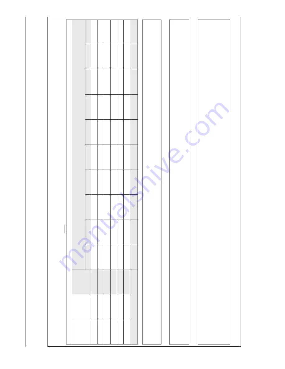
TABLE 11
SUPPLEMENT
AL ORIFICE SIZE CHAR
T
90 Plus ONL
Y
models with 15,000 Btu's per Burner
. DO NO
T
USE
THIS CHAR
T FOR ANY 80 PLUS MODEL.
NA
TURAL
GAS QUICK REFERENCE CHAR
T
FOR ORIFICE SELECTION,
AT
3.5" W
.C.
AND
APPROXIMA
TE FINAL
FIRING RA
TES
Final Firing Rate per Burner
Sea Level Orifice
Size
Sea Level
Cubic Foot at
3.5" W
.C.
90 Plus Heat
Value at
15,000 Btu’
s
per Burner
0-999
1000-1999
2000-2999
3000-3999
4000-4999
5000-5999
6000-6999
7000-7999
8000-8999
9000-9999
ELEV
ATION CHAR
T
(National Fuel Gas Code recommended
orifice based on 4% derate for each 10
00 foot of elevation, based
on the intersection
of the orifice required at Sea Level and the elevation required below)
46
18.57
808
46
46
47
47
47
48
48
49
49
50
47
17.52
856
47
47
48
48
49
49
49
50
50
51
48
16.36
917
48
48
49
49
49
50
50
50
51
51
49
15.2
987
49
49
50
50
50
51
51
51
52
52
50
13.92
1078
50
50
51
51
51
51
52
52
52
53
51
12.77
1175
51
51
51
52
52
52
52
53
53
53
15,000
14,400
13,800
13,200
12,600
12,000
11,400
10,800
10,200
9,600
All calculations
are perf
ormed b
y
using the fir
st three columns of inf
ormation
onl
y.
Bef
ore beginning
an
y
calculations,
determine
the
individual
burner Btu siz
e
and heating v
alue at Sea Le
vel f
or the installation
site
. Eac
h v
alue sho
wn in the Heat
Value column is per
burner at 3.5"
W
.C.
NO
TE:
Heat V
alue at Sea Level, for the location of the installation,
is
available from the Natural Gas Supplier to that site. Orifices for all altitudes are based
on Sea Level values.
Divide the individual burner capacity (15,000 for 90 plus) by
the Heat V
alue for the site to determine
the Cubic Foot value at Sea Level, or divide
burner capacity by
the Cubic Foot value for the Heat V
alue. Once you have either the Cubic Foot V
alue or the Heat V
alue you can estimate the Sea
Level orifice for the site.
To
select the corresponding
high altitude orifice, locate the site elevation on t
he chart above and the orifice required at Sea
Level from your calculation in the first column.
The correct high altitude orifice that must be installed in each individual burner is
the intersection
of
these two points on the chart above.
Summary of Contents for RGFE
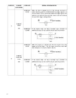
Page 92: ...92 TABLE 21 FURNACE FAULT CODES EXPANDED W DESCRIPTIONS AND SOLUTIONS CONTINUED ...
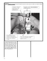
Page 93: ...93 TABLE 21 FURNACE FAULT CODES EXPANDED W DESCRIPTIONS AND SOLUTIONS CONTINUED ...
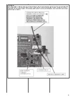
Page 94: ...94 TABLE 21 FURNACE FAULT CODES EXPANDED W DESCRIPTIONS AND SOLUTIONS CONTINUED ...
Page 95: ...95 TABLE 21 FURNACE FAULT CODES EXPANDED W DESCRIPTIONS AND SOLUTIONS CONTINUED ...
Page 96: ...96 TABLE 21 FURNACE FAULT CODES EXPANDED W DESCRIPTIONS AND SOLUTIONS CONTINUED ...
Page 97: ...97 TABLE 21 FURNACE FAULT CODES EXPANDED W DESCRIPTIONS AND SOLUTIONS CONTINUED ...
Page 98: ...98 TABLE 21 FURNACE FAULT CODES EXPANDED W DESCRIPTIONS AND SOLUTIONS CONTINUED ...
Page 99: ...99 TABLE 21 FURNACE FAULT CODES EXPANDED W DESCRIPTIONS AND SOLUTIONS CONTINUED ...
Page 102: ...102 TABLE 21 FURNACE FAULT CODES EXPANDED W DESCRIPTIONS AND SOLUTIONS CONTINUED ...
Page 103: ...103 TABLE 21 FURNACE FAULT CODES EXPANDED W DESCRIPTIONS AND SOLUTIONS CONTINUED ...
Page 104: ...104 TABLE 21 FURNACE FAULT CODES EXPANDED W DESCRIPTIONS AND SOLUTIONS CONTINUED ...
Page 105: ...105 TABLE 21 FURNACE FAULT CODES EXPANDED W DESCRIPTIONS AND SOLUTIONS CONTINUED ...

