111
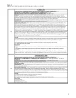
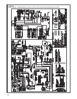
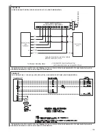
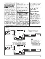
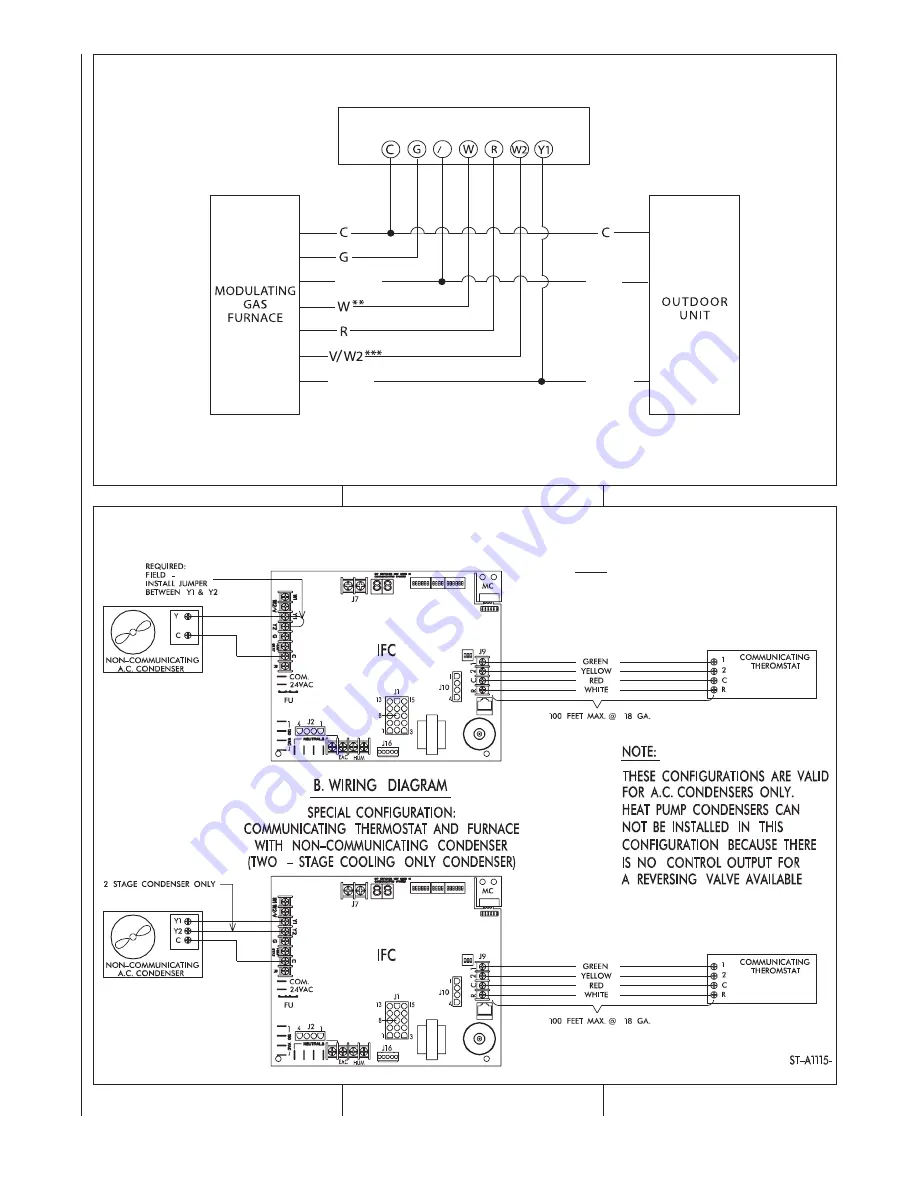
FIGURE 90
WIRING DIAGRAM FROM TWO-STAGE HEAT (NON-COMMUNICATING)
*
NO MECHANICAL THERMOSTATS.
** 40% FIRING RATE IN TWO-STAGE OPERATION
(DIP SWITCH SET SW2 — SWITCHES 1 & 2 ON).
*** 65% and 100% FIRING RATE IN TWO-STAGE OPERATION (W & W2 ENERGIZED).
**** 2 STAGE COOLING ONLY.
Y
H
(Y
2
)
Y (Y
2
)
Y
L
(Y
1
)
Y
L
(Y
1
)
****
****
Y Y
2
2-STAGE ELECTRONIC THERMOSTAT*
(NON-COMMUNICATING)
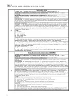
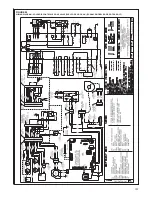
FIGURE 91
WIRING DIAGRAM – SPECIAL CONFIGURATION: COMMUNICATING THERMOSTAT AND FURNACE WITH NON-COMMUNICATING CONDENSER
NOTE:
DEHUMIDIFICATION FUNCTION FROM A
COMMUNICATING THERMOSTAT WILL NOT
BE POSSIBLE WITH THIS CONFIGURATION.
Summary of Contents for RGFE
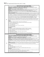
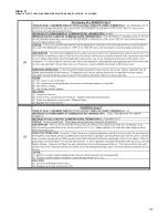
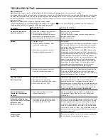
Page 92: ...92 TABLE 21 FURNACE FAULT CODES EXPANDED W DESCRIPTIONS AND SOLUTIONS CONTINUED ...
Page 93: ...93 TABLE 21 FURNACE FAULT CODES EXPANDED W DESCRIPTIONS AND SOLUTIONS CONTINUED ...
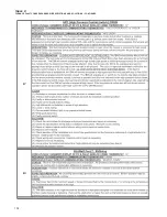
Page 94: ...94 TABLE 21 FURNACE FAULT CODES EXPANDED W DESCRIPTIONS AND SOLUTIONS CONTINUED ...
Page 95: ...95 TABLE 21 FURNACE FAULT CODES EXPANDED W DESCRIPTIONS AND SOLUTIONS CONTINUED ...
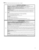
Page 96: ...96 TABLE 21 FURNACE FAULT CODES EXPANDED W DESCRIPTIONS AND SOLUTIONS CONTINUED ...
Page 97: ...97 TABLE 21 FURNACE FAULT CODES EXPANDED W DESCRIPTIONS AND SOLUTIONS CONTINUED ...
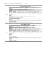
Page 98: ...98 TABLE 21 FURNACE FAULT CODES EXPANDED W DESCRIPTIONS AND SOLUTIONS CONTINUED ...
Page 99: ...99 TABLE 21 FURNACE FAULT CODES EXPANDED W DESCRIPTIONS AND SOLUTIONS CONTINUED ...
Page 102: ...102 TABLE 21 FURNACE FAULT CODES EXPANDED W DESCRIPTIONS AND SOLUTIONS CONTINUED ...
Page 103: ...103 TABLE 21 FURNACE FAULT CODES EXPANDED W DESCRIPTIONS AND SOLUTIONS CONTINUED ...
Page 104: ...104 TABLE 21 FURNACE FAULT CODES EXPANDED W DESCRIPTIONS AND SOLUTIONS CONTINUED ...
Page 105: ...105 TABLE 21 FURNACE FAULT CODES EXPANDED W DESCRIPTIONS AND SOLUTIONS CONTINUED ...


