70
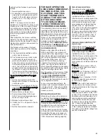
switches until the rise range is as close
as possible to the target temperature
rise (65°F or 55°F – adjusted at dip-
switch SW1-3).
Three examples of airflow adjustment
are shown below.
NOTE: All dip switches on SW3 will be
shipped in the “OFF” position.
E
x
ample 1
PROBLEM:
Temperature rise is too
high at 40% firing rate although it is
within the published range at 100% fir-
ing rate.
SOLUTION:
More airflow is needed to
lower the temperature rise at 40%.
1) Set dip switches 4 and 5 of SW3 to
the “ON” position. This will produce a
7.5% increase in blower output.
2) Allow furnace to run for several min-
utes at 40% firing rate until temperature
probes reach equilibrium.
3) If the temperature rise is still above
the published range, set switch 6 of
SW3 to the “ON” position. This will
increase the airflow rate from +7.5% to
+15% above the standard value.
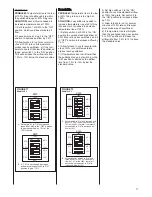
Placing SW2-4 in the “ON” position will
establish the low (Y1) cooling airflow at
½ of the max cool (Y2) airflow. This set-
ting will be useful with cooling systems
where two compressors are used to
control two cooling stages (one com-
pressor for first stage and two compres-
sors for second stage).
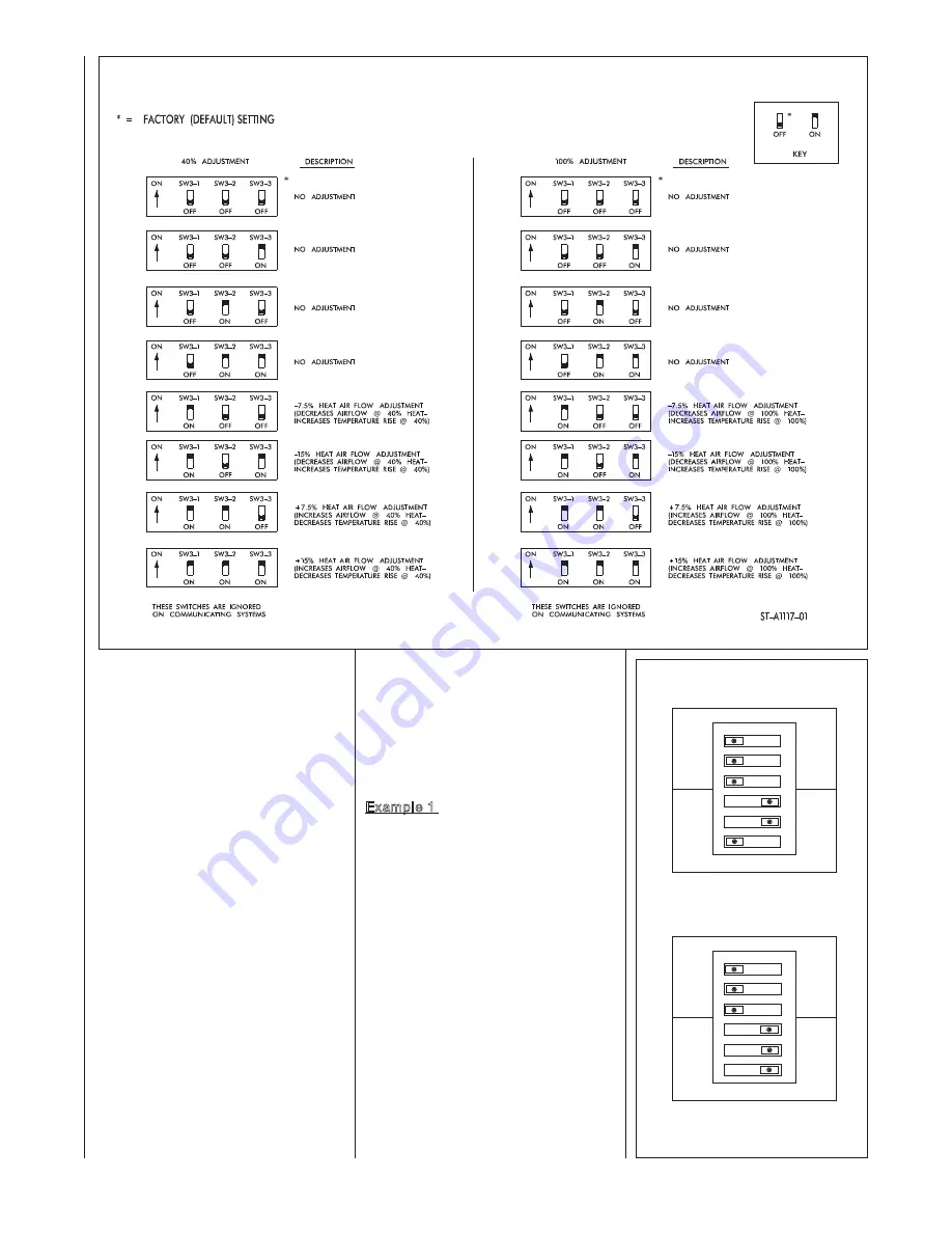
SW3
Dipswitch bank SW3 is used to fine-tune
the airflow in the heating mode. The
switches of bank SW3 can be set to
adjust either the minimum heat rate air-
flow or the maximum heat rate airflow or
both. Also, every firing rate in between
these points will be adjusted according-
ly.
SW3 will allow for airflow adjustments at
high altitude, improper temperature
probe locations, or no temperature
probe applications. If the temperature
rise range needs adjustment, the techni-
cian must use separate temperature
probes to determine the rise range and
adjust the airflow using SW3’s dip
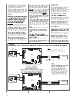
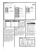
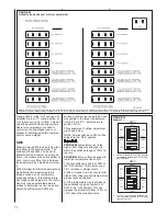
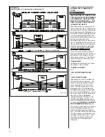
FIGURE 69
DIPSWITCH BANK SW3 HEAT AIRFLOW ADJUSTMENT
FIGURE 70
EXAMPLE 1
123456
ON
OFF
40%
100%
SW3
STD
--
7.5%
STD
--
7.5%
ADJ
+
15%
ADJ
+
15%
A. Set switches 4 & 5 to “ON” position
to increase airflow by 7.5% at the
40% fire rate.
123456
ON
OFF
40%
100%
SW3
STD
--
7.5%
STD
--
7.5%
ADJ
+
15%
ADJ
+
15%
B. If +7.5% is not enough, increase air-
flow by setting switch 6 to “ON” posi-
tion to give +15%.
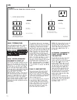
NOTE:
TO CLEAR FAULT CODES IN THE FURNACE CONTROL, TURN SWITCH # SW3-3 ON, OFF, ON, OFF OR OFF, ON, OFF, ON WITHIN 30 SECONDS. THE RIGHT-MOST SEVEN-SEGMENT DISPLAY WILL FLASH THE UPPER
AND LOWER HORIZONTAL MEMBERS ONCE AS CONFIRMATION THAT THE FAULTS HAVE BEEN CLEARED. BE SURE TO RETURN THE DIPSWITCH (SW3-3) TO ITS ORIGINAL POSITION AFTER CLEARING THE FAULTS.
Summary of Contents for RGFE
Page 92: ...92 TABLE 21 FURNACE FAULT CODES EXPANDED W DESCRIPTIONS AND SOLUTIONS CONTINUED ...
Page 93: ...93 TABLE 21 FURNACE FAULT CODES EXPANDED W DESCRIPTIONS AND SOLUTIONS CONTINUED ...
Page 94: ...94 TABLE 21 FURNACE FAULT CODES EXPANDED W DESCRIPTIONS AND SOLUTIONS CONTINUED ...
Page 95: ...95 TABLE 21 FURNACE FAULT CODES EXPANDED W DESCRIPTIONS AND SOLUTIONS CONTINUED ...
Page 96: ...96 TABLE 21 FURNACE FAULT CODES EXPANDED W DESCRIPTIONS AND SOLUTIONS CONTINUED ...
Page 97: ...97 TABLE 21 FURNACE FAULT CODES EXPANDED W DESCRIPTIONS AND SOLUTIONS CONTINUED ...
Page 98: ...98 TABLE 21 FURNACE FAULT CODES EXPANDED W DESCRIPTIONS AND SOLUTIONS CONTINUED ...
Page 99: ...99 TABLE 21 FURNACE FAULT CODES EXPANDED W DESCRIPTIONS AND SOLUTIONS CONTINUED ...
Page 102: ...102 TABLE 21 FURNACE FAULT CODES EXPANDED W DESCRIPTIONS AND SOLUTIONS CONTINUED ...
Page 103: ...103 TABLE 21 FURNACE FAULT CODES EXPANDED W DESCRIPTIONS AND SOLUTIONS CONTINUED ...
Page 104: ...104 TABLE 21 FURNACE FAULT CODES EXPANDED W DESCRIPTIONS AND SOLUTIONS CONTINUED ...
Page 105: ...105 TABLE 21 FURNACE FAULT CODES EXPANDED W DESCRIPTIONS AND SOLUTIONS CONTINUED ...

