checked when converting the furnace
for LP operation. Figures 46 and 47
below show the incorrect way and the
correct way to install the jumper. The
jumper well is located next to the
adjustment well (with “+” and “–” text
and two-headed arrow) and will be
covered by a sticker or label. To con-
vert to LP the label over the jumper
well will need to be removed.
SETTING GAS PRESSURE
A properly calibrated pressure gauge
or U-Tube manometer is required for
accurate gas pressure measure-
ments.
ELEVATIONS ABOVE 2000 FT
REQUIRE THAT THE FURNACE
INPUT RATING BE ADJUSTED
AND THAT THE SIZE OF THE
BURNER ORIFICES BE RE-CAL-
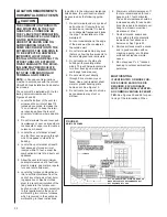
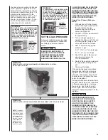
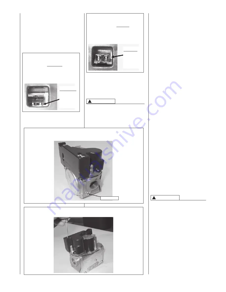
FIGURE 48
SERVO-CONTROLLED GAS VALVE MANIFOLD PRESSURE TAP LOCATION
(FUEL CODE: HA OR HB)
CULATED BASED ON ELEVATION
AND GAS HEATING VALUE. THE
BURNER ORIFICES MAY (OR MAY
NOT) NEED TO BE CHANGED. SEE
THE SECTION TITLED “HIGH ALTI-
TUDE INSTALLATIONS” OF THIS
BOOK FOR INSTRUCTIONS.
Supply Gas Pressure Measure-
ment.
1. With gas shut off to the furnace
at the manual gas valve outside
the unit, remove the line
pressure tap plug on the gas
valve. See Figure 48.
2. Connect a U-Tube manometer to
the pressure tap.
3. Turn on the gas supply and
operate the furnace at 100% and
all other gas-fired units on the
same gas line as the furnace.
4. Note or adjust the supply-line
pressure to give:
A. 5" - 10.5" w.c. for natural gas.
B. 11" - 13" w.c. for LP gas.
5. Shut off the gas at the manual
gas valve and remove the
U-Tube manometer.
6. Replace the supply-line pressure
tap plug before turning on the
gas.
7. Check unit for leaks.
If the supply-line pressure is above
these ranges, install an in-line gas
regulator to the furnace for natural
gas units. With LP gas, have the LP
supplier reduce the supply-line pres-
sure at the regulator.
If supply-line pressure is below these
ranges, either remove any restrictions
in the gas supply piping or enlarge
the gas pipe. See Tables 8 and 9.
With LP gas, have the LP supplier
adjust the su
pply-line pressure at the
regulator.
ELEVATIONS ABOVE 2000 FT
REQUIRE THAT THE FURNACE
INPUT RATING BE ADJUSTED
AND THAT THE SIZE OF THE
BURNER ORIFICES BE RE-CAL-
CULATED BASED ON ELEVATION
AND GAS HEATING VALUE. THE
BURNER ORIFICES MAY (OR MAY
NOT) NEED TO BE CHANGED. SEE
THE SECTION TITLED “HIGH ALTI-
TUDE INSTALLATIONS” OF THIS
BOOK FOR INSTRUCTIONS.
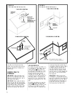
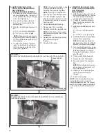
FIGURE 49
SERVO CONTROLLED GAS VALVE PRESSURE ADJUSTMENT (FUEL CODE: HA OR HB)
CAUTION
!
CAUTION
!
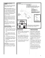
FIGURE 46
LP JUMPER INSTALLED ON SERVO MODU-
LATING GAS VALVE WITH PINS NOT CON-
NECTED. THIS IS INCORRECT. MAKE
SURE THAT THE JUMPER CONNECTS THE
TWO PINS TOGETHER AND VERIFY MANI-
FOLD GAS PRESSURE AT HIGH FIRE TO
MAKE SURE THE VALVE IS PROPERLY
CONVERTED FOR LP GAS
JUMPER
IMPROPERLY
INSTALLED.
NOTE THAT
PINS ARE
NOT CON-
NECTED.
FIGURE 47
LP JUMPER INSTALLED ON SERVO MODU-
LATING GAS VALVE WITH PINS PROPERLY
CONNECTED. THIS IS CORRECT. MAKE
SURE THAT THE JUMPER CONNECTS THE
TWO PINS TOGETHER AND VERIFY MANI-
FOLD GAS PRESSURE AT HIGH FIRE TO
MAKE SURE THAT THE VALVE IS PROPER-
LY CONVERTED FOR LP GAS
JUMPER
PROPERLY
INSTALLED.
NOTE THAT
PINS ARE
CONNECTED.
MANIFOLD TAP
43
NOTE:
The adjust-
ment wheel will not
stop rotating when
it hits the maximum
or minimum posi-
tion. Instead, it will
continue to rotate
to the opposite
adjustment. Use
the letters on the
wheel as a guide.
Summary of Contents for RGFE
Page 92: ...92 TABLE 21 FURNACE FAULT CODES EXPANDED W DESCRIPTIONS AND SOLUTIONS CONTINUED ...
Page 93: ...93 TABLE 21 FURNACE FAULT CODES EXPANDED W DESCRIPTIONS AND SOLUTIONS CONTINUED ...
Page 94: ...94 TABLE 21 FURNACE FAULT CODES EXPANDED W DESCRIPTIONS AND SOLUTIONS CONTINUED ...
Page 95: ...95 TABLE 21 FURNACE FAULT CODES EXPANDED W DESCRIPTIONS AND SOLUTIONS CONTINUED ...
Page 96: ...96 TABLE 21 FURNACE FAULT CODES EXPANDED W DESCRIPTIONS AND SOLUTIONS CONTINUED ...
Page 97: ...97 TABLE 21 FURNACE FAULT CODES EXPANDED W DESCRIPTIONS AND SOLUTIONS CONTINUED ...
Page 98: ...98 TABLE 21 FURNACE FAULT CODES EXPANDED W DESCRIPTIONS AND SOLUTIONS CONTINUED ...
Page 99: ...99 TABLE 21 FURNACE FAULT CODES EXPANDED W DESCRIPTIONS AND SOLUTIONS CONTINUED ...
Page 102: ...102 TABLE 21 FURNACE FAULT CODES EXPANDED W DESCRIPTIONS AND SOLUTIONS CONTINUED ...
Page 103: ...103 TABLE 21 FURNACE FAULT CODES EXPANDED W DESCRIPTIONS AND SOLUTIONS CONTINUED ...
Page 104: ...104 TABLE 21 FURNACE FAULT CODES EXPANDED W DESCRIPTIONS AND SOLUTIONS CONTINUED ...
Page 105: ...105 TABLE 21 FURNACE FAULT CODES EXPANDED W DESCRIPTIONS AND SOLUTIONS CONTINUED ...

