6
➤
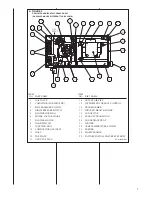
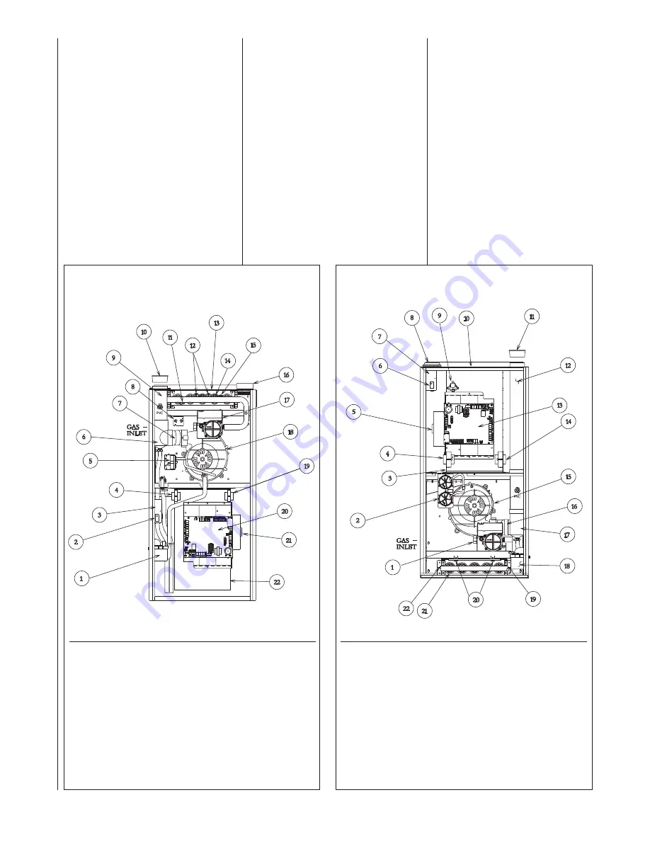
FIGURE 2
DOWNFLOW FURNACE RGGE
(GAS VALVE MAY BE DIFFERENT THAN SHOWN)
GENERAL INFORMATION
The RGFE, RGGE and RGJF series
furnaces are design-certified by CSA
for use with natural and L.P. gases as
follows:
• As direct vent, central forced air
furnaces with all combustion air
supplied directly to the furnace
burners through a special air intake
system outlined in these instruc-
tions.
• As non-direct, central forced air fur-
nace taking combustion air from
the installation area or using air
ducted from the outside.
•
IMPORTANT:
Proper application,
installation and maintenance of this
FIGURE 1
UPFLOW FURNACE RGFE
(GAS VALVE MAY BE DIFFERENT THAN SHOWN)
furnace are required if consumers
are to receive the full benefits for
which they have paid.
Install this furnace in accordance with
the American National Standard
Z223.1 – latest edition entitled
“National Fuel Gas Code” (NFPA54,
90A and 90B) and requirements or
codes of the local utilities or other
authorities having jurisdiction. This is
available from the following:
National Fire Protection
Association, Inc.
Batterymarch Park
Quincy, MA 02269
CSA International - U.S.
8501 East Pleasant Valley Road
Cleveland, Ohio, 44131
Canadian installations must be
installed in accordance with CSA,
local installation codes and
authorities having jurisdiction.
CSA is available from:
CSA International - Canada
178 Rexdale Blvd.
Etobicoke (Toronto), Ontario,
Canada M9W-1R3
ITEM
NO. PART NAME
1
CONDENSATE TRAP
2
DOOR SWITCH
3
JUNCTION BOX
4
TRANSFORMER
5
PRESSURE SWITCH ASSEMBLY
6
EXHAUST TRANSITION
7
CONNECTOR
8
MAIN LIMIT
9
EXHAUST AIR PIPE
10 VENT CAP SHIPPING PLUG
11 FLAME SENSOR
12 OVERTEMPERATURE SWITCH
ITEM
NO. PART NAME
13 TOP PLATE
14 BURNER
15 IGNITER
16 COMBUSTION AIR INLET
17 GAS VALVE
18 INDUCED DRAFT BLOWER
19 POWER FACTOR CHOKE
20 INTEGRATED FURNACE CONTROL
21 BLOWER MOTOR
22 BLOWER HOUSING
ITEM
NO. PART NAME
1
GAS VALVE
2
PRESSURE SWITCH ASSEMBLY
3
BLOWER HOUSING
4
POWER FACTOR CHOKE
5
BLOWER MOTOR
6
DOOR SWITCH
7
JUNCTION BOX
8
COMBUSTION AIR INLET
9
HALC
10 TOP PLATE
11 VENT CAP SHIPPING PLUG
12 OUTLET AIR PIPE
ITEM
NO. PART NAME
13 INTEGRATED FURNACE CONTROL
14 TRANSFORMER
15 INDUCED DRAFT BLOWER
16 CONNECTOR
17 EXHAUST TRANSITION
18 CONDENSATE TRAP
19 IGNITER
20 OVERTEMPERATURE SWITCH
21 BURNER
22 FLAME SENSOR
ST-A1123-01_1
ST-A1123-01_2
Summary of Contents for RGFE
Page 92: ...92 TABLE 21 FURNACE FAULT CODES EXPANDED W DESCRIPTIONS AND SOLUTIONS CONTINUED ...
Page 93: ...93 TABLE 21 FURNACE FAULT CODES EXPANDED W DESCRIPTIONS AND SOLUTIONS CONTINUED ...
Page 94: ...94 TABLE 21 FURNACE FAULT CODES EXPANDED W DESCRIPTIONS AND SOLUTIONS CONTINUED ...
Page 95: ...95 TABLE 21 FURNACE FAULT CODES EXPANDED W DESCRIPTIONS AND SOLUTIONS CONTINUED ...
Page 96: ...96 TABLE 21 FURNACE FAULT CODES EXPANDED W DESCRIPTIONS AND SOLUTIONS CONTINUED ...
Page 97: ...97 TABLE 21 FURNACE FAULT CODES EXPANDED W DESCRIPTIONS AND SOLUTIONS CONTINUED ...
Page 98: ...98 TABLE 21 FURNACE FAULT CODES EXPANDED W DESCRIPTIONS AND SOLUTIONS CONTINUED ...
Page 99: ...99 TABLE 21 FURNACE FAULT CODES EXPANDED W DESCRIPTIONS AND SOLUTIONS CONTINUED ...
Page 102: ...102 TABLE 21 FURNACE FAULT CODES EXPANDED W DESCRIPTIONS AND SOLUTIONS CONTINUED ...
Page 103: ...103 TABLE 21 FURNACE FAULT CODES EXPANDED W DESCRIPTIONS AND SOLUTIONS CONTINUED ...
Page 104: ...104 TABLE 21 FURNACE FAULT CODES EXPANDED W DESCRIPTIONS AND SOLUTIONS CONTINUED ...
Page 105: ...105 TABLE 21 FURNACE FAULT CODES EXPANDED W DESCRIPTIONS AND SOLUTIONS CONTINUED ...


