54
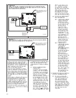
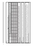
Evaporator coil must be the same width as the furnace OR one size larger in width than the gas furnace.
(See condenser spec. sheet, I&O and other literature for evaporator selection)
Evaporator coil must be the same width as the furnace OR one size larger in width than the gas furnace.
(See condenser spec. sheet, I&O and other literature for evaporator selection)
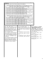
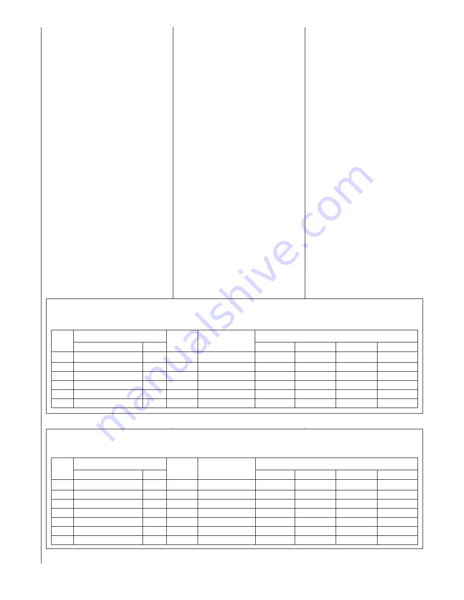
TABLE 14
AIRFLOW AND CONDENSER SELECTION – PREMIUM (NON-COMMUNICATING) COOLING SYSTEMS (2 STAGE COOL)
(NOTE: SWITCH SW2-4 OF THE IFC MUST BE IN THE “OFF” POSITION FOR OPTIMUM PERFORMANCE)
TABLE 13
AIRFLOW AND CONDENSER SELECTION – PREMIUM (NON-COMMUNICATING) COOLING SYSTEMS (1 STAGE COOL ONLY)
(NOTE: SWITCH SW2-4 OF THE IFC MUST BE IN THE “OFF” POSITION FOR OPTIMUM PERFORMANCE)
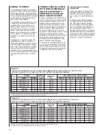
ZONING SYSTEMS
The manufacturer does not currently
provide or support zoning with modulat-
ing furnace. However, zoning systems
can be installed with the system as long
as the zoning equipment manufacturers
specifications and installation instruc-
tions are met and followed.
The preferred zoning method is to use
a “bypass” system which is properly
installed for maximum efficiency. In
these systems, excess
air is routed
back through the system to be used
again – this is opposed to a “dump”
system in which excess air is routed to
a zone where it is expected that the
extra heat or cooling would be least
noticed.
If installed as a “bypass” system, the
installation must have an optional
freeze stat installed to prevent the coil
from icing with excess bypass cooling.
Also, if the zoning equipment manufac-
turer provides a limit switch (usually
provided by the zoning manufacturer),
this limit must be installed in the system
to prevent the furnace from overheat-
ing.
FURNACE INSTALLATION
WITH NON-COMMUNICAT-
ING HIGH-EFFICIENCY
PREMIUM COOLING OR
HEAT PUMP SYSTEMS
Furnace installation with Rheem/Ruud
-ASL or -ARL outdoor condensing units
can provide high efficiency (up to 16
SEER) cooling operation when com-
bined with proper evaporator coil. For
listed cooling equipment combinations,
see the -ARA or -ARL specification
sheets and Tables 13 and 14 of this
document. Using Tables 13 and 14 and
literature provided with the cooling
equipment, the installer needs to make
sure that the proper evaporator coil,
condensing coil and airflow is config-
ured to achieve rated efficiency.
In accordance with Rheem/Ruud cool-
ing equipment installation instructions,
do not install an evaporator coil or coil
casing to the furnace which is smaller
in width than the furnace cabinet.
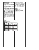
TONS
FURNACE
MODEL
WIDTH
APPROX.
AIRFLOW
(CFM)
SW-1,#1
SW-1,#2
SW-1,#3
SW-1,#4
CONDENSING
UNIT
MOD. FURNACE IFC DIP-SWITCH SETTINGS
2
-GFE/GGE-06 & -07
17.5"
800
-ARA-24
OFF
ON
OFF
OFF
2-1/2
-GFE/GGE-06 & -07*
17.5"
1000
-ARA-30
ON
OFF
OFF
OFF
3
-GFE/GGE-09 & -10*
21"
1200
-ARA-36
ON
ON
OFF
OFF
3-1/2
-GFE/GGE-09 & -10*
21"
1400
-ARA-42
ON
ON
OFF
OFF
3
-GFE/GGE-12
24.5"
1200
-ARA-36
ON
ON
OFF
OFF
3-1/2
-GFE/GGE-12
24.5"
1400
-ARA-42
ON
ON
OFF
OFF
TONS
FURNACE
MODEL
WIDTH
APPROX.
AIRFLOW
(CFM)
SW-1,#1
SW-1,#2
SW-1,#3
SW-1,#4
CONDENSING
UNIT
MOD. FURNACE IFC DIP-SWITCH SETTINGS
2
-GFE/GGE-06 & -07
17.5"
800
-ARL/ASL-24
OFF
ON
OFF
OFF
3
-GFE/GGE-06 & -07
17.5"
1200
-ARL/ASL-36
OFF
OFF
OFF
OFF
3
-GFE/GGE-09 & -10
21"
1200
-ARL/ASL-36
ON
ON
OFF
OFF
3
-GFE/GGE-12
24.5"
1200
-ARL/ASL-36
ON
ON
OFF
OFF
4
-GFE/GGE-09 & -10
21"
1600
-ARL/ASL-48
ON
OFF
OFF
OFF
4
-GFE/GGE-12
24.5"
1600
-ARL/ASL-48
ON
OFF
OFF
OFF
5
-GFE/GGE-12
24.5"
1800
-ARL/ASL-60
OFF
OFF
OFF
OFF
UP TO 16 SEER COOLING
OPERATION
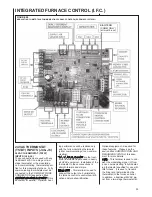
Check the revision number of the
integrated furnace control (IFC) to
determine how best to configure
your furnace for high SEER opera-
tion.
To achieve high SEER operation,
turn dip switch #4 of bank SW2 to
the “off” position (factory setting).
This will enable the furnace opera-
tion for 16 SEER. Actual SEER val-
ues will vary and depend on the
equipment combination. Consult the
specifications sheets and installation
instructions of the cooling equipment
purchased for a listing of the SEER
ratings for a specific combination.
Summary of Contents for RGFE
Page 92: ...92 TABLE 21 FURNACE FAULT CODES EXPANDED W DESCRIPTIONS AND SOLUTIONS CONTINUED ...
Page 93: ...93 TABLE 21 FURNACE FAULT CODES EXPANDED W DESCRIPTIONS AND SOLUTIONS CONTINUED ...
Page 94: ...94 TABLE 21 FURNACE FAULT CODES EXPANDED W DESCRIPTIONS AND SOLUTIONS CONTINUED ...
Page 95: ...95 TABLE 21 FURNACE FAULT CODES EXPANDED W DESCRIPTIONS AND SOLUTIONS CONTINUED ...
Page 96: ...96 TABLE 21 FURNACE FAULT CODES EXPANDED W DESCRIPTIONS AND SOLUTIONS CONTINUED ...
Page 97: ...97 TABLE 21 FURNACE FAULT CODES EXPANDED W DESCRIPTIONS AND SOLUTIONS CONTINUED ...
Page 98: ...98 TABLE 21 FURNACE FAULT CODES EXPANDED W DESCRIPTIONS AND SOLUTIONS CONTINUED ...
Page 99: ...99 TABLE 21 FURNACE FAULT CODES EXPANDED W DESCRIPTIONS AND SOLUTIONS CONTINUED ...
Page 102: ...102 TABLE 21 FURNACE FAULT CODES EXPANDED W DESCRIPTIONS AND SOLUTIONS CONTINUED ...
Page 103: ...103 TABLE 21 FURNACE FAULT CODES EXPANDED W DESCRIPTIONS AND SOLUTIONS CONTINUED ...
Page 104: ...104 TABLE 21 FURNACE FAULT CODES EXPANDED W DESCRIPTIONS AND SOLUTIONS CONTINUED ...
Page 105: ...105 TABLE 21 FURNACE FAULT CODES EXPANDED W DESCRIPTIONS AND SOLUTIONS CONTINUED ...

