86
IMPORTANT:
It is recommended that
at the beginning of the heating sea-
son, the flame sensor be cleaned with
steel wool by a qualified installer, ser-
vice agency or the gas supplier.
IMPORTANT:
It is recommended that
at the beginning of the heating sea-
son, the condensate trap be inspect-
ed for debris or blockage. A blocked
condensate trap can cause water to
back up into the primary heat
exchanger and lea
d to nuisance trip-
ping of the over temperature switches
and/or pressure switches.
IMPORTANT:
It is recommended that
at the beginning of the heating sea-
son, the condensate neutralizer (if
used) be replaced by a qualified
installer, service agency or the gas
supplier.
IMPORTANT:
Drain traps will often
dry out over a summer. During annual
inspection the service person must
verify that the trap still has water. If
there is not enough water (or no
water) in the trap, the service person
must fill it to the appropriate level.
IMPORTANT:
It is recommended that
an annual inspection and cleaning of
all furnace markings be made to
assure legibility. Attach a replacement
marking, which can be obtained
through the distributor, if any are
found to be illegible or missing.
REPLACEMENT PARTS
Contact your local distributor for a
complete parts list.
TROUBLESHOOTING
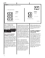
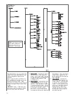
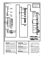
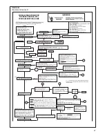
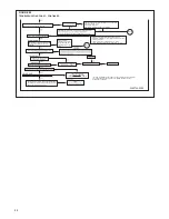
Figure 82 is a troubleshooting flow-
charts for the sequence of operation.
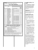
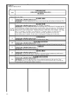
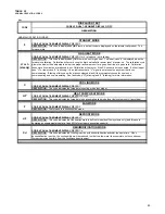
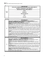
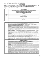
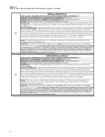
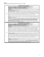
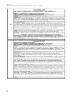
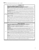
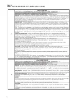
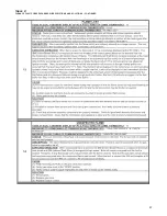
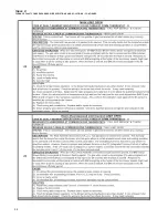
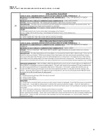
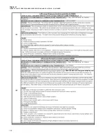
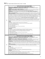
Table 21 is for fault-code descriptions.
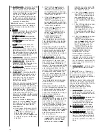
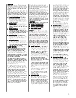
WIRING DIAGRAM
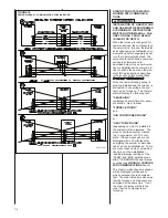
Figures 83 and 84 are complete
wiring diagrams for the furnace and
power sources.
DO NOT OPERATE THE SYSTEM
WITHOUT FILTERS. A PORTION
OF THE DUST ENTRAINED IN THE
AIR MAY TEMPORARILY LODGE
IN THE AIR DUCT RUNS AND AT
THE SUPPLY REGISTERS. ANY
RECIRCULATED DUST PARTI-
CLES WILL BE HEATED AND
CHARRED BY CONTACT WITH
THE FURNACE HEAT EXCHANG-
ER. THIS RESIDUE WILL SOIL
CEILINGS, WALLS, DRAPES,
CARPETS AND OTHER HOUSE-
HOLD ARTICLES.
LUBRICATION
IMPORTANT:
Do Not attempt to lubri-
cate the bearings on the blower motor or
the induced draft blower motor. Addition
of lubricants can reduce the motor life
and void the warranty.
The blower motor and induced draft
blower motor bearings are prelubricated
by the manufacturer and do not require
further attention.
The blower motor and induced draft
blower motor must be cleaned periodi-
cally by a qualified installer, service
agency, or the gas supplier to prevent
the possibility of overheating due to an
accumulation of dust and dirt on the
windings or on the motor exterior. The
air filters should be kept clean. As dirty
filters can restrict airflow. The motor
depends upon sufficient airflowing
across and through it to keep from over-
heating.
SYSTEM OPERATION
INFORMATION
Advise The Customer
IMPORTANT:
Replace all blower doors
and compartment covers after servicing
the furnace. Do not operate the unit
without all panels and doors securely in
place.
1. Keep the air filters clean. The heat-
ing system will operate more effi-
ciently and more economically.
2. Arrange the furniture and drapes so
that the supply air registers and the
return air grilles are unobstructed.
3. Close doors and windows. This will
reduce the heating load on the sys-
tem.
4. Avoid excessive use of kitchen
exhaust fans.
5. Do not permit the heat generated
by television, lamps or radios to
influence the thermostat operation.
6. Explain proper operation of the
system with constant air circulation.
ANNUAL INSPECTION
The furnace should operate for many
years without excessive scale build-up
in the flue passageways. However, it is
recommended that a qualified installer,
service agency, or the gas supplier
annually inspect the flue passageways,
the vent system and the main burners
for continued safe operation. Pay partic-
ular attention to deterioration from cor-
rosion or other sources.
During the annual inspection, all electri-
cal power to the furnace should be
turned off and then restored. This will
put the furnace into a calibration cycle
on the initial call for heat. This is a five
minute (or until the heat call is satisfied)
cycle which allows the furnace to evalu-
ate conditions It should be noted, that a
calibration cycle will occur on the initial
call for heat each time after line voltage
has been interrupted to the unit.
IMPORTANT:
It is recommended that at
the beginning and at approximately half
way through the heating season, a visu-
al inspection be made of the main burn-
er flames for the desired flame appear-
ance by a qualified installer, service
agency or the gas supplier. If the flames
are distorted and/or there is evidence of
back pressure, check the vent and inlet
air system for blockage. If there is car-
bon and scale in the heat exchanger
tubes, the heat exchanger assembly
should be replaced.
HOLES IN THE VENT PIPE OR HEAT
EXCHANGER CAN CAUSE TOXIC
FUMES TO ENTER THE HOME,
RESULTING IN CARBON MONOXIDE
POISONING OR DEATH. THE VENT
PIPE OR HEAT EXCHANGER MUST
BE REPLACED IF THEY LEAK.
!
CAUTION
!
WARNING
Summary of Contents for RGFE
Page 92: ...92 TABLE 21 FURNACE FAULT CODES EXPANDED W DESCRIPTIONS AND SOLUTIONS CONTINUED ...
Page 93: ...93 TABLE 21 FURNACE FAULT CODES EXPANDED W DESCRIPTIONS AND SOLUTIONS CONTINUED ...
Page 94: ...94 TABLE 21 FURNACE FAULT CODES EXPANDED W DESCRIPTIONS AND SOLUTIONS CONTINUED ...
Page 95: ...95 TABLE 21 FURNACE FAULT CODES EXPANDED W DESCRIPTIONS AND SOLUTIONS CONTINUED ...
Page 96: ...96 TABLE 21 FURNACE FAULT CODES EXPANDED W DESCRIPTIONS AND SOLUTIONS CONTINUED ...
Page 97: ...97 TABLE 21 FURNACE FAULT CODES EXPANDED W DESCRIPTIONS AND SOLUTIONS CONTINUED ...
Page 98: ...98 TABLE 21 FURNACE FAULT CODES EXPANDED W DESCRIPTIONS AND SOLUTIONS CONTINUED ...
Page 99: ...99 TABLE 21 FURNACE FAULT CODES EXPANDED W DESCRIPTIONS AND SOLUTIONS CONTINUED ...
Page 102: ...102 TABLE 21 FURNACE FAULT CODES EXPANDED W DESCRIPTIONS AND SOLUTIONS CONTINUED ...
Page 103: ...103 TABLE 21 FURNACE FAULT CODES EXPANDED W DESCRIPTIONS AND SOLUTIONS CONTINUED ...
Page 104: ...104 TABLE 21 FURNACE FAULT CODES EXPANDED W DESCRIPTIONS AND SOLUTIONS CONTINUED ...
Page 105: ...105 TABLE 21 FURNACE FAULT CODES EXPANDED W DESCRIPTIONS AND SOLUTIONS CONTINUED ...

