SUPPLY AIR SENSOR
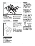
Each furnace comes shipped from the
factory with a supply air sensor. Install
the sensor, in the supply air plenum
trunk, with two, field supplied, #8 sheet
metal screws, using the following guide-
lines:
1. 12” downstream of the evaporator
coil, if installed.
2. If no evaporator coil is used, locate
the sensor out of direct line-of-site
of the heat exchanger and
not clos-
er than 18” downstream of the fur-
nace outlet.
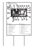
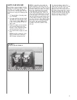
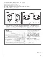
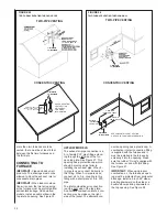
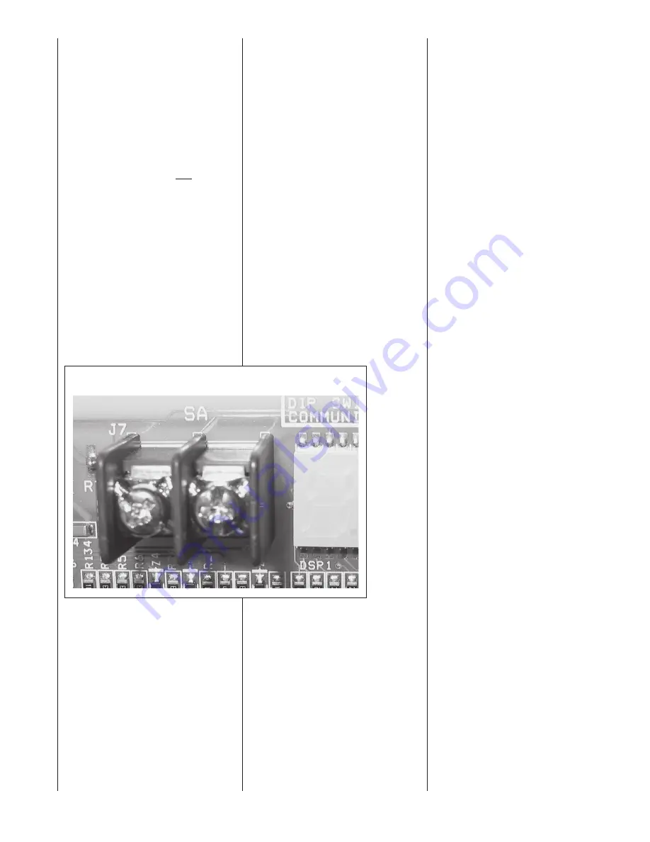
3. Attach the supply air sensor wires
onto the terminals marked “SA
Sensor” on the integrated furnace
control board (See Figure 13).
4. Do not extend the supply-air sensor
wire.
NOTE:
Improper placement of the
supply air sensor can adversely
affect furnace temperature rise.
NOTE:
In downflow circumstances
where building construction does not
allow for the placement of the sensor to
fall within these parameters, the supply
air sensor should not be connected.
This means that the furnace will run
under default parameters. When run-
ning under default parameters, the “82”
code will appear for 90 seconds. After
that, the fault code will be stored in the
control board’s memory and will show
only upon power cycling. Default airflow
parameters can be manually adjusted.
See section discussing Integrated
Furnace Control (IFC) board in this
manual.
For communicating systems, the
supply air sensor input can be turned
off so that a fault code will not be
displayed at all. This can be done in
the furnace setup menu of a commu-
nicating thermostat. See the section
of this manual titled Communicating
Systems under sub-section titled
Furnace User Menus (Setup).
FIGURE 13
SUPPLY AIR SENSOR TERMINALS
17
Summary of Contents for RGFE
Page 92: ...92 TABLE 21 FURNACE FAULT CODES EXPANDED W DESCRIPTIONS AND SOLUTIONS CONTINUED ...
Page 93: ...93 TABLE 21 FURNACE FAULT CODES EXPANDED W DESCRIPTIONS AND SOLUTIONS CONTINUED ...
Page 94: ...94 TABLE 21 FURNACE FAULT CODES EXPANDED W DESCRIPTIONS AND SOLUTIONS CONTINUED ...
Page 95: ...95 TABLE 21 FURNACE FAULT CODES EXPANDED W DESCRIPTIONS AND SOLUTIONS CONTINUED ...
Page 96: ...96 TABLE 21 FURNACE FAULT CODES EXPANDED W DESCRIPTIONS AND SOLUTIONS CONTINUED ...
Page 97: ...97 TABLE 21 FURNACE FAULT CODES EXPANDED W DESCRIPTIONS AND SOLUTIONS CONTINUED ...
Page 98: ...98 TABLE 21 FURNACE FAULT CODES EXPANDED W DESCRIPTIONS AND SOLUTIONS CONTINUED ...
Page 99: ...99 TABLE 21 FURNACE FAULT CODES EXPANDED W DESCRIPTIONS AND SOLUTIONS CONTINUED ...
Page 102: ...102 TABLE 21 FURNACE FAULT CODES EXPANDED W DESCRIPTIONS AND SOLUTIONS CONTINUED ...
Page 103: ...103 TABLE 21 FURNACE FAULT CODES EXPANDED W DESCRIPTIONS AND SOLUTIONS CONTINUED ...
Page 104: ...104 TABLE 21 FURNACE FAULT CODES EXPANDED W DESCRIPTIONS AND SOLUTIONS CONTINUED ...
Page 105: ...105 TABLE 21 FURNACE FAULT CODES EXPANDED W DESCRIPTIONS AND SOLUTIONS CONTINUED ...


