78
attached (or not sensed), NA
will be displayed in the “SUP-
PLY TEMP” selection.
b. If the S.A.S. is not turned on
(see “SUPPLY AIR SENS” in
“SETUP” menu below) and a
sensor is attached, a valid
temperature will be displayed
in the “SUPPLY TEMP” selec-
tion.
c. If the S.A.S. is turned on (see
“SUPPLY AIR SENS” in
“SETUP” menu below) and a
sensor is attached, a valid
temperature will be displayed
in the “SUPPLY TEMP” selec-
tion.
d. If the S.A.S. is turned on (see
“SUPPLY AIR SENS” in
“SETUP” menu below) and a
sensor is not attached (or not
sensed), the text “FLT” (for
FauLT) is displayed in the
“SUPPLY TEMP” selection.
*ALL TEMPERATURES CAN
BE DISPLAYED ONLY IN
FAHRENHEIT VALUES
Note: Supply Air (SA) and
Return Air (RA) temperature
readings may not be accurate in
standby mode. These should
only be read and used when the
blower is running in heat, cool or
other modes.
9. HUM OUTPUT
– Indicates when
the humidifier output is turned
on.
“2 WK HIST”
menu – This menu
gives information about the number
of cycles and the amount of time
spent in various modes of operation
over the last 14 days.
NOTE:
For both 2 WK & LIFE HIST,
the value saved prior to power loss
may not include information from the
last hour of operation. This is
because the information is only
stored once every hour.
1. MOD HT HRS
– Indicates the
number of hours of operation of
gas heating operation rate in the
last 14 days.
2. MOD HT CYCLS – Indicates the
number of cycles of operation
(i.e.: the number of times it
turned on and off) of gas heat
operation in the last 14 days.
3. BLOWER HRS – Indicates the
number of hours of continuous
fan operation in the last 14 days.
4. BLOWER CYCLS – Indicates
the number of cycles of opera-
tion (i.e.: the number of times it
turned on and off) of the contin-
uous fan operation in the last 14
days.
b. If the S.A.S. is not turned on
(see “SUPPLY AIR SENS” in
“SETUP” menu below) and a
sensor is attached, a valid tem-
perature will be displayed in the
“TEMP DIFF” selection.
c. If the S.A.S. is turned on (see
“SUPPLY AIR SENS” in
“SETUP” menu below) and a
sensor is attached, a valid tem-
perature will be displayed in the
“TEMP DIFF” selection.
d. If the S.A.S. is turned on (see
“SUPPLY AIR SENS” in
“SETUP” menu below) and a
sensor is not attached (or not
sensed), the text “FLT” (for
FauLT) is displayed in the
“TEMP DIFF” selection
*ALL TEMPERATURES WITHIN
THE USER MENUS CAN BE DIS-
PLAYED ONLY IN FAHRENHEIT
VALUES
Note: Supply Air (SA) and Return
Air (RA) temperature readings may
not be accurate in standby mode.
These should only be read and
used when the blower is running in
heat, cool or other modes.
7. RETURN TEMP*
– Indicates the
temperature of the return air in the
return air duct. This menu item
may not be accurate when the Air
Circulating Blower (ACB) is not
turning. This value is sensed at the
furnace control (IFC) and not at an
external sensor attached to the
control. If the temperature can not
be sensed for some reason, the
text “FLT” will be displayed. This
temperature is displayed in degrees
F and can not be changed to
Celsius units
*ALL TEMPERATURES CAN BE
DISPLAYED ONLY IN FAHREN-
HEIT VALUES
Note: Supply Air (SA) and Return
Air (RA) temperature readings may
not be accurate in standby mode.
These should only be read and
used when the blower is running in
heat, cool or other modes.
8. SUPPLY TEMP*
– Indicates the
temperature of the supply air in the
supply air duct. This menu item
may not be accurate when the Air
Circulating Blower (ACB) is not
turning. This value is sensed at an
external sensor attached to the
control. This temperature is dis-
played in degrees F and can not be
changed to Celsius units. A few
different conditions that apply to
this menu item are:
a. If the Supply Air Sensor (S.A.S.)
is not turned on (see “SUPPLY
AIR SENS” in “SETUP” menu
below) and a sensor is not
10. BLOWER CFM
– Indicates the CFM
that the furnace control requests
from the blower motor. This value
may vary somewhat from the actual
values, but it should be very close.
The value can also be tracked
through the blinking decimal point
on the seven segment displays at
the furnace control (although with
not as much resolution).
“STATUS 2”
menu – This menu also
gives information about the status of
certain furnace components and fea-
tures.
1. MODE – Indicates the current state
of operation of the furnace. The
possibilities are listed below:
a. MOD HEAT – Heat operation
b. AC – Air conditioning operation.
c. FAN ONLY – Continuous fan
operation.
d. HP – Heat-pump operation.
2. MOTOR MFGR
– Indicates the
manufacturer of the main air-circu-
lating blower motor. At the time of
this publication there are two possi-
bilities; RGBLT for Regal Beloit (for-
merly GE) and EMERSON.
3. MOTOR RPM
– Indicates the RPM
of the main circulating air blower.
4. MAXIMUM CFM
– Indicates the
maximum CFM that the main circu-
lating air blower can deliver.
5. BLOWER CFM
– Indicates the out-
put of airflow in CFM of the main cir-
culating air blower.
6. TEMP DIFF*
– Indicates the differ-
ence between the outlet duct and
inlet duct air temperatures. This
menu item may not be accurate
when the Air Circulating Blower
(ACB) is not turning.
When the outlet air (supply) temper-
ature is greater than the inlet air
(return) temperature, the thermostat
will display the text “RISE” with the
temperature value. Conversely,
when the outlet air (supply) temper-
ature is less than the inlet air
(return) temperature, the thermostat
will display the text “DROP” with the
temperature value.
This temperature is displayed in
degrees F and can not be changed
to Celsius units. A few other differ-
ent conditions that apply to this
menu item are:
a. If the Supply Air Sensor (S.A.S.)
is not turned on (see “SUPPLY
AIR SENS” in “SETUP” menu
below) and a sensor is not
attached (or not sensed), NA will
be displayed in the “TEMP DIFF”
selection.
Summary of Contents for RGFE
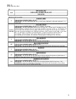
Page 92: ...92 TABLE 21 FURNACE FAULT CODES EXPANDED W DESCRIPTIONS AND SOLUTIONS CONTINUED ...
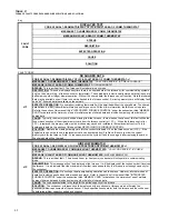
Page 93: ...93 TABLE 21 FURNACE FAULT CODES EXPANDED W DESCRIPTIONS AND SOLUTIONS CONTINUED ...
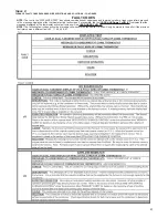
Page 94: ...94 TABLE 21 FURNACE FAULT CODES EXPANDED W DESCRIPTIONS AND SOLUTIONS CONTINUED ...
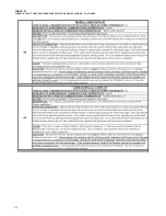
Page 95: ...95 TABLE 21 FURNACE FAULT CODES EXPANDED W DESCRIPTIONS AND SOLUTIONS CONTINUED ...
Page 96: ...96 TABLE 21 FURNACE FAULT CODES EXPANDED W DESCRIPTIONS AND SOLUTIONS CONTINUED ...
Page 97: ...97 TABLE 21 FURNACE FAULT CODES EXPANDED W DESCRIPTIONS AND SOLUTIONS CONTINUED ...
Page 98: ...98 TABLE 21 FURNACE FAULT CODES EXPANDED W DESCRIPTIONS AND SOLUTIONS CONTINUED ...
Page 99: ...99 TABLE 21 FURNACE FAULT CODES EXPANDED W DESCRIPTIONS AND SOLUTIONS CONTINUED ...
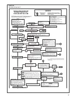
Page 102: ...102 TABLE 21 FURNACE FAULT CODES EXPANDED W DESCRIPTIONS AND SOLUTIONS CONTINUED ...
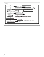
Page 103: ...103 TABLE 21 FURNACE FAULT CODES EXPANDED W DESCRIPTIONS AND SOLUTIONS CONTINUED ...
Page 104: ...104 TABLE 21 FURNACE FAULT CODES EXPANDED W DESCRIPTIONS AND SOLUTIONS CONTINUED ...
Page 105: ...105 TABLE 21 FURNACE FAULT CODES EXPANDED W DESCRIPTIONS AND SOLUTIONS CONTINUED ...

