background image

84

ESPLXD-ET Controller

Weather Signal

Verify the status of the radio signal from your local weather 
station.

A  Weather  Reach

TM

  Signal  Provider  retrieves  weather  information 

from local weather stations. The information is broadcast as a weather 
signal via a paging radio frequency to your ET Manager Cartridge. The 
weather signal contains the most recent weather conditions including: 
solar energy, temperature, wind, humidity, and rainfall.

b

g

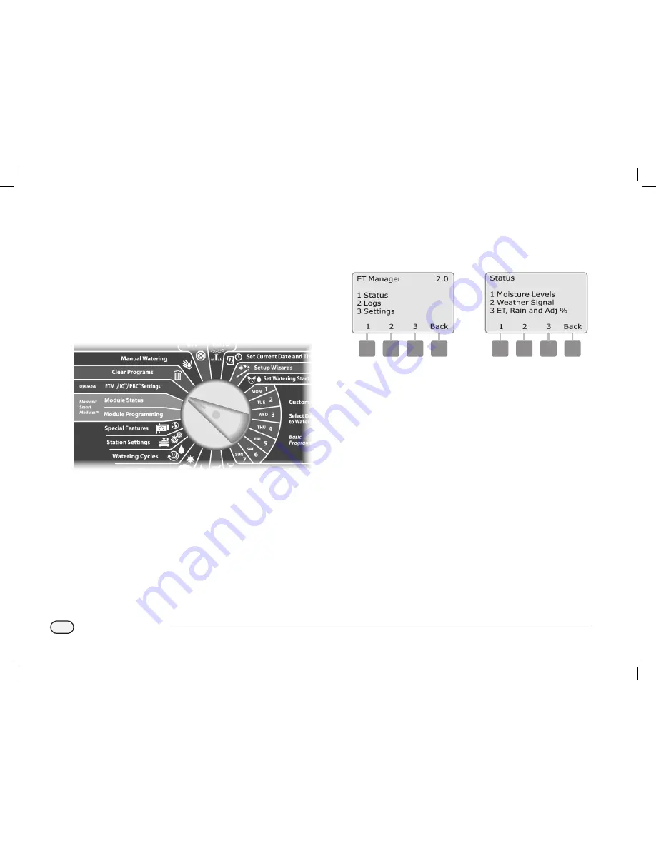
Turn  the  controller  dial  to  ETM

TM

/IQ

TM

  (or  ETM

TM

/IQ

TM

/PBC

TM

Settings; then press 

Menu

.

The  ET  Manager  screen  appears.  Press  the 

1

  button  to  select 

Status.

The Status screen appears. Press the 

2

 button to select Weather 

Signal.

a

b

ESPLXD-ET user-manual (670504-01) artwork_120716.indb   84

7/16/2012   3:48:27 PM

Summary of Contents for ESPLXD-ET

Page 1: ...ESPLXD ET Controller Installation Programming Operation Guide ESPLXD ET user manual 670504 01 artwork_120716 indb 1 7 16 2012 3 48 00 PM...

Page 2: ...th local regulations c c WARNING You must use special precautions when valve wires also known as station or solenoid wires are located adjacent to or share a conduit with other wires such as wires use...

Page 3: ...Up Programs 12 Set Up Programs Optional 12 Set Up ET Manager Cartridge 12 Review Setup 12 Optional Setup 12 AUTO 13 Automatic Operation 13 Alarm Conditions 14 Decoder Address Alarms 14 FloWatchTM Alar...

Page 4: ...ation or MV Decoder 56 Interpreting Ping Results 56 Ping Sensor Decoder 57 Weather Sensor Status 58 Master Valve Status 59 ET Manager Alert Messages 60 Landscape Condition Issues 63 Section D Advanced...

Page 5: ...nd Recall Programs 124 Section E Options Special Features 125 Backup and Recall Programs 125 Store Default Programs 125 Recall Default Programs 126 Delayed Recall 127 Programming Backup Cartridge PBC...

Page 6: ...m Stations 156 View and Clear Flow Alarms 158 View Station Flow Alarms 158 View FloZoneTM Flow Alarms 159 Clear Flow Alarms 160 View Flow Rates 161 View Flow Rates for Stations 161 View Flow Rates for...

Page 7: ...Installation 196 Install the Local Rain Gauge 196 Connect the Local Rain Gauge 196 Connect Decoders to Field Wiring 197 Wire Splices 197 Field Decoder Connections 198 Master Valves and MV Decoders 19...

Page 8: ...this page intentionally left blank ESPLXD ET user manual 670504 01 artwork_120716 indb 6 7 16 2012 3 48 01 PM...

Page 9: ...r data to automatically adjust irrigation schedules to reduce water consumption by watering only when the plants need it Controller Features The ESPLXD ET controller has a variety of advanced features...

Page 10: ...larm Conditions for more details on how to review and clear alarms Controls Switches and Indicators Key operational features of the ESPLXD ET Controller front panel A Programming Dial Used for program...

Page 11: ...our landscape needs b b NOTE To find your local Weather ReachTM Signal Provider you can create a site specific Schedule Report using the ET Manager Scheduler software found on the ET Manager Resource...

Page 12: ...labeled products are independently certified to meet the EPA s water efficiency and performance criteria The criteria for irrigation controllers is based on the industry s SmartWater Application Tech...

Page 13: ...ht Red Blinking Power is present communication between ESPLXD ET Controller and ET Manager Cartridge is absent Lower light Red Blinking Power is present communication between the controller and ET Man...

Page 14: ...n A Star Pattern allows branching as often as necessary without ever looping the wire back to the controller This generally allows more design flexibility but at the expense of some distance The dista...

Page 15: ...e Size Ohms per 1000 or Ohms per Km per conductor Max Length For Critical Path Star Loop Km Miles Km Miles 2 5 mm2 7 5 Ohms Km 3 00 1 86 12 00 7 46 14 AWG 2 58 Ohms 1000 2 66 1 65 10 63 6 61 12 AWG 1...

Page 16: ...sor The ESPLXD ET controller can also interface to a local sensor such as a rain shutoff device The local weather sensor connects directly to the ESP LXD M50 module via a separate wired or wireless co...

Page 17: ...t times as specified by irrigation programs The controller sends signals to the appropriate decoder powering the valve solenoid to open or close When additional stations are scheduled another signal i...

Page 18: ...the time that the first station in the program begins watering all other stations in the program then follow in sequence b b NOTE The term start time refers to the time that a program starts not to t...

Page 19: ...ing with it We recommend hanging it on the hook inside the controller cabinet door as shown below Remote Programming The ESPLXD ET controller can be programmed while operating under battery power This...

Page 20: ...s A B C D 4 4Select program A B C or D Page 20 4 4Set watering start times Page 31 4 4Select watering days Page 32 4 4Set station run time s Page 33 See Watering Cycles dial position for Odd Odd31 Eve...

Page 21: ...dial to AUTO A The Auto screen is displayed with the current day and time shown B WhenaprogramisrunninginAUTOmode thestationnumberwill display on the screen Press the or buttons to add or subtract min...

Page 22: ...nflowconditionsifyouhaveFloWatch set up See Section F Flow Management for more details Review Alarm Messages A When an alarm condition is detected the alarm light on the controller front panel will il...

Page 23: ...programs you have loaded into the controller g g Turn the controller dial to AUTO A Open the controller outer cabinet door and inner front panel B Locate the RESET button on the back of the front pane...

Page 24: ...button is to restart the cartridge s internal programming and re enable communications with the ET Manager Receiver b b NOTE Resetting the ET Manager Cartridge does not affect internally stored data...

Page 25: ...with 50 stations available This can easily be expanded by adding one or two optional ESP LXD SM75 Station Modules Each station module adds 75 additional stations to increase capacity to 125 or 200 sta...

Page 26: ...18 ESPLXD ET Controller this page intentionally left blank ESPLXD ET user manual 670504 01 artwork_120716 indb 18 7 16 2012 3 48 07 PM...

Page 27: ...Be sure to set the hour correctly to either AM or PM l l Press and HOLD buttons to accelerate settings for hours and minutes B Press the and buttons to set the current minute then press Next 1 2 C Pr...

Page 28: ...specific information you enter such as start times or watering days will affect only the selected program Setup Wizards Setup Wizards take you through each step for setting up your hardware in the ESP...

Page 29: ...orts Select your valve type if present then press Next 3 4 b b NOTE Rain Bird residential valves DV and JTV series are not compatible with ESPLXD ET decoders Use Rain Bird commercial valves PGA PEB GB...

Page 30: ...er valves g g Turn the controller dial to Setup Wizards A The Setup Wizards screen appears Press the Down Arrow button to select Master Valves then press Next B The Master Valve Setup screen appears P...

Page 31: ...o continue 5 6 G On the FloZone assignment screen press the and buttons to associate the MV with the appropriate FloZone then press Next b b NOTE A FloZone can use more than one MV as it s source s bu...

Page 32: ...er dial to Setup Wizards A The Setup Wizards screen appears Press the Down Arrow button to select Weather Sensors then press Next B The Weather Sensor Setup screen appears Press the and buttons to ent...

Page 33: ...e Section H Weather Sensor Installation for more details Custom Pause Sensors When a weather condition becomes true a Custom Pause sensor will stop irrigation and also stop the irrigation timer When t...

Page 34: ...ctions to set up valve types master valves and weather sensors if present g g Turn the controller dial to Setup Wizards A The Setup Wizards screen appears Press the Down Arrow button to select Station...

Page 35: ...es if you re using either the FloWatch or FloManager features Press the and buttons to see available FloZones or if you re not using FloZones select zero then press Next 5 6 b b NOTE If you have alrea...

Page 36: ...xt B The Flow Sensor Setup screen appears Press the and buttons to enter the desired flow sensor number then press Next 1 2 C Press the and buttons to enter the decoder address pressing Next and Back...

Page 37: ...he number setting fields then press Next b b NOTE An alarm will show if a duplicate sensor decoder address is entered for more than one flow sensor See Section A Alarm Conditions for more details D Pr...

Page 38: ...o the flow sensor is displayed Press Next 7 e e Repeat this process to set up additional custom flow sensors Be sure to note each flow sensor on your Programming Guide for future reference ESPLXD ET u...

Page 39: ...to Set Watering Start Times A The Set Start Times screen appears Press the and buttons to set Start Time for the current program then press Next l l Press and HOLD buttons to accelerate settings for h...

Page 40: ...ected as a watering day if possible The ET Manager will change the Seasonal Adjust percentages depending on the weather conditions g g Turn the controller dial to Mon 1 A The Custom screen appears Pre...

Page 41: ...weather conditions g g Turn the controller dial to Set Station Run Times A The Set Run Times screen appears Press the and buttons to enter the station to program then press Next b b NOTE If the desire...

Page 42: ...Signal Provider Information Sheet l l Signal Provider Code l l Weather Region number l l Approximate Elevation l l Average Daily Historical ET values for each Month used as backup data Irrigation Amou...

Page 43: ...e l l What if any areas are on a slope l l Is my landscape generally healthy Answers to the preceding questions and information gathered from completing the Site AssessmentWorksheet will help guide yo...

Page 44: ...ailed and helpful instructions on creating a Schedule Report and should be used as a reference when creating a Schedule Report Use the information from your Site Assessment Worksheet to fill in the Sc...

Page 45: ...ick Next in the bottom right corner b b NOTE As each tab is completed a new tab is created at the top of the page for future reference e e REPEAT Step 2 for each new tab until all tabs are complete b...

Page 46: ...ill be created Save the Schedule Report to your computer You can create a different schedule for as many irrigation sites as you need and retrieve any file in the future to add or update the schedule...

Page 47: ...e purchased the ET Manager Programming Software the summary from the Scheduler Software can be sent directly to the ET Manager Cartridge through your computer Refer to the ET Manager Programming Softw...

Page 48: ...The Signal Provider Code screen appears Press the and buttons to enter the value for A Press Next to move to the next letter When the value for every letter is entered press Next a b C The Weather Re...

Page 49: ...s in the Weather Signal section Setup a Local Rain Gauge If you have installed the Local Rain Gauge ETM RG you must set the ET Manager Cartridge Rain Source to ETM RG by following the steps in the Rai...

Page 50: ...42 ESPLXD ET Controller this page intentionally left blank ESPLXD ET user manual 670504 01 artwork_120716 indb 42 7 16 2012 3 48 15 PM...

Page 51: ...elected press Next B The Confirm Programs screen appears with Program Summary selected press Next 1 2 C The Program Summary screen appears providing a summary of Run Times Start Times and water days f...

Page 52: ...art times displayed for the currently selected program Press Next b b NOTE If the desired program is not selected use the Program Select switch to change it See Section B Program Select Switch for mor...

Page 53: ...played Press Next J The Calendar Day Off review screen appears with all selected calendar days off displayed Press Next i j K The Station Delay review screen appears with delay time between stations d...

Page 54: ...n operate simultaneously for that program are displayed Press Next o p Q The Maximum Number of SimulStations for controller review screen appears with the maximum number of stations that can operate s...

Page 55: ...yed for the currently selected program b b NOTE If the desired program is not selected use the Program Select switch to change it See Section B Program Select Switch for more details 3 b b NOTE For st...

Page 56: ...then press Next 1 2 C The Sta Run Time Per Day screen appears with total Run Time displayed for the currently selected station in all four programs For programs where a particular station is not used...

Page 57: ...ions Check System A The System Diagnostics screen appears Press the Down Arrow button to select Test All stations then press Next B The Test All stations screen appears Press the and buttons to adjust...

Page 58: ...will irrigate prior to medium priority stations and medium priority stations will irrigate prior to lower priority stations See Section B Station Setup and Confirm Programs for more details 2 RunaTest...

Page 59: ...irmation screen appears stating that irrigation has been disabled F A second confirmation screen appears showing that Short Finding is now On and in progress 5 6 b b NOTE Use a clamp meter to isolate...

Page 60: ...hen press Next 1 2 C A confirmation screen appears press Start D A second confirmation screen appears to confirm the Decoder Test is In Progress 3 4 E The DecoderTest Result screen appears If no issue...

Page 61: ...53 ESPLXD ET Controller this page intentionally left blank ESPLXD ET user manual 670504 01 artwork_120716 indb 53 7 16 2012 3 48 18 PM...

Page 62: ...decoders X 17 5 mA Quantity of other SD210 decoders X 8 0 mA Approximate total system amperage in mA Single address station decoders include the FD 101 FD 102 decoders Multiple address station decode...

Page 63: ...ulations detailed above for both A and B Three flags also appear below the voltage and amperage readings For a normal healthy system the flags should typically read OK abnormal readings will cause the...

Page 64: ...rs then press Next 1 2 C The Ping Decoder screen appears with Station Decoder selected Press Next to ping a Station decoder or else press the Down Arrow button to select MV Decoder then press Next D T...

Page 65: ...ars Press the Down Arrow button to select Ping Decoders then press Next 1 2 C The Ping Decoder screen appears Press the Down Arrow button to select Sensor Decoder then press Next D The Ping Sensor Dec...

Page 66: ...installation has not been completed or the sensor is not linked to any stations c PAUSING current weather condition has caused the sensor to pause irrigation d PREVENTING current weather condition ha...

Page 67: ...Check System A The System Diagnostics screen appears Press the Down Arrow button to select Wthr Sensor Status then press Next B The MV Status screen appears showing installed master valves and their c...

Page 68: ...al Provider information sheet and from the Historical ET database included in the ET Manager Cartridge Resource CD Look up your city and state then program the monthly values into the ET Manager Cartr...

Page 69: ...A calculated ET value based on previously received weather information and the historical ET programmed in your ET Manager will be used No Paging Signal Detected The ET Manager Cartridge verifies the...

Page 70: ...idge has detected a radio failure this message will appear The radio may need to be re initialized To do so press the Reset button on the ET Manager Cartridge If the problem persists the ET Manager Re...

Page 71: ...ESP LX Controller Adding or subtracting time for the station where the spot appears may compensate for minor irrigation system inefficiencies NOTE Manual watering to a dry spot will speed recovery Ad...

Page 72: ...y ET rates are high enough that daily watering is necessary no action is required The Irrigation Amount s are programmed too low The Minimum Run Time Limit is programmed too low The Irrigation Amounts...

Page 73: ...d rain for the last hour is 1 00 only 0 25 will be added to the Moisture Level The Saturation Allowance may be too low Change the Saturation Allowance to a higher amount to accept more rainfall in the...

Page 74: ...ocal Rain Gauge ETM RG Check the Weather Info for the last hour of rain to verify the rain data is being reported by your ET Manager Cartridge Check the Rain Source to verify the ET Manager Cartridge...

Page 75: ...and can significantly impact irrigation For example if you set a program level Seasonal Adjustment of 10 and then a monthly Seasonal Adjustment of 10 then irrigation will be reduced to 1 of normal 10...

Page 76: ...st then press Next D Press the and buttons to set the Seasonal Adjustment percentage from 0 300 l l Press and HOLD buttons to accelerate settings for percentages 3 4 Repeat this process to set Seasona...

Page 77: ...creen appears Press the Down Arrow button to select Select PGMs then press Next 1 2 C Press the Yes or No buttons to set Monthly Adjust for the current selected program D To set another program change...

Page 78: ...o your controller it may be unnecessary to manually program a Rain Delay Consult the rain sensor device documentation for more details g g Turn the controller dial to Delay Watering A The Delay Wateri...

Page 79: ...e DelayWatering screen appears Press the Down Arrow button to select Calendar Day Off then press Next B The Calendar Day off screen appears showing up to 5 scheduled calendar days off in chronological...

Page 80: ...within the Water Window See Section A Watering Start Times for more details Set Up Water Window g g Turn the controller dial to Delay Watering A The DelayWatering screen appears Press the Down Arrow...

Page 81: ...select allowed irrigation days carefully to avoid landscape damage in case irrigation delays are lengthy b b NOTE A watering cycle is selected as soon as it is highlighted with the cursor b b NOTE Ev...

Page 82: ...red 3 e e Change the Program Select switch and repeat this process to set Watering Cycles for other programs as desired b b NOTE Watering day selections carry over to Watering Days dial positions and...

Page 83: ...first date for the Watering Cycle to begin then press Next l l Press and HOLD buttons to accelerate settings for dates D The Watering Day Cycle screen appears Press the Yes button to allow irrigation...

Page 84: ...with Cycle Soak selected press Next B The Cycle Soak screen appears Press the and buttons to enter the desired station number then press Next 1 2 C Press the and buttons to set the Cycle time between...

Page 85: ...to Station Settings A The Station Settings screen appears Press the Down Arrow button to select Station Delay then press Next B The Delay Between stations screen appears Press the and buttons to set t...

Page 86: ...setting program level and LXD level SimulStations to a fairly high number This will allow FloManager to provide maximum irrigation based on your system s hydraulic capacity Consult the FloManager por...

Page 87: ...r of SimulStations screen appears Press the and buttons to set the maximum number of irrigation stations from 1 to 8 that can operate simultaneously then press Next D Press the and buttons to set the...

Page 88: ...time Longest run time shortest run time 3 Station number 1 2 3 4 Program assignment A B C D b b NOTE If FloManager is turned ON then the default Station Sequencing setting is Sequence by Station Prior...

Page 89: ...81 ESPLXD ET Controller this page intentionally left blank ESPLXD ET user manual 670504 01 artwork_120716 indb 81 7 16 2012 3 48 26 PM...

Page 90: ...m settings to customize cartridge operation When the ESPLXD ET Controller dial is set to the ETMTM IQTM or ETMTM IQTM PBCTM Setting position the display and soft keys are controlled by the ET Manager...

Page 91: ...rn the controller dial to ETMTM IQTM or ETMTM IQTM PBCTM Settings A The Moisture Levels screen appears The current Moisture Level is indicated graphically for each program Press the Adj button to view...

Page 92: ...requency to your ET Manager Cartridge The weather signal contains the most recent weather conditions including solar energy temperature wind humidity and rainfall g g Turn the controller dial to ETMTM...

Page 93: ...ls b b NOTE If the activation status shows Not Activated contact your Weather ReachTM Signal Provider to establish services You will need to provide the Weather ReachTM Signal Provider with the ET Man...

Page 94: ...the last hour day week and two week period are available g g Turn the controller dial to ETMTM IQTM or ETMTM IQTM PBCTM Settings then press Menu A The ET Manager screen appears Press the 1 button to...

Page 95: ...87 ESPLXD ET Controller E The Seasonal Adjust screen appears e ESPLXD ET user manual 670504 01 artwork_120716 indb 87 7 16 2012 3 48 28 PM...

Page 96: ...hat only 2 of the 3 start times for a given program are necessary the number of watering days added to this log will be 0 66 2 3 of a typical watering day g g Turn the controller dial to ETMTM IQTM or...

Page 97: ...l reset the Last date to None Days Watered and Total Water to 0 00 and the Since date to the current date Press Next to view the next program s Irrigation Log e ESPLXD ET user manual 670504 01 artwork...

Page 98: ...terrupt cleared When the ET Manager issues a weather interrupt the alarm light on the ESPLXD ET controller is illuminated g g Turn the controller dial to ETMTM IQTM or ETMTM IQTM PBCTM Settings then p...

Page 99: ...the 2 button to select Logs B The Logs screen appears Press the 3 button to select Weather Information a b C TheWeather Information screen appears Press More to see more details 3 D The Rain screen ap...

Page 100: ...d landscape b b To determine Irrigation Amounts refer to the ET Manager Schedule Report or see the Irrigation Amount and Station Run Times section in the Appendix g g Turn the controller dial to ETMTM...

Page 101: ...ered based on evapotranspiration such as landscape lighting or a fountain feature must be set to Non ET This is set by pressing the button until 0 00 is displayed then pressing the button one more tim...

Page 102: ...your site use the ET Manager Scheduler Software located on the ET Manager Resource CD g g Turn the controller dial to ETMTM IQTM or ETMTM IQTM PBCTM Settings then press Menu A The ET Manager screen a...

Page 103: ...95 ESPLXD ET Controller this page intentionally left blank ESPLXD ET user manual 670504 01 artwork_120716 indb 95 7 16 2012 3 48 31 PM...

Page 104: ...t 120 The Maximum RunTime determines the longest watering run time that can be applied to your landscape There may be instances where your landscape has dried out more than a regular watering cycle wi...

Page 105: ...s the and buttons to set the desired percentage then press Next b b NOTE To follow best water management practices of deep less frequent watering set the percentage at or above 80 3 4 E The Maximum Ru...

Page 106: ...sely represents the location of the ESPLXD ET Controller and irrigation site b b NOTE To find your Weather Region number refer to the ET Manager Schedule Report or the Weather ReachTM Signal Provider...

Page 107: ...99 ESPLXD ET Controller E The Weather Region screen appears Press the and buttons to enter the Weather Region number e ESPLXD ET user manual 670504 01 artwork_120716 indb 99 7 16 2012 3 48 32 PM...

Page 108: ...Similar to the Weather Region number a Rain Region number corresponds to a local rain station that tracks local rainfall and is also accessed by the Weather ReachTM Signal Provider b b NOTE To determ...

Page 109: ...101 ESPLXD ET Controller E The Rain Source screen appears Press the and buttons until Weather Signal is selected e ESPLXD ET user manual 670504 01 artwork_120716 indb 101 7 16 2012 3 48 33 PM...

Page 110: ...button to select System Settings a b C The System Setting screen appears Press the 1 button to select Data Source D The Data Source screen appears Press the 2 button to select Rain Source 3 4 E The R...

Page 111: ...the 2 button to select System Settings a b C The System Setting screen appears Press the 1 button to select Data Source D The Data Source screen appears Press the 2 button to select Rain Source c d E...

Page 112: ...ignal Provider Code refer to the ET Manager Schedule Report or the Weather ReachTM Signal Provider Information Sheet available at www rainbird com wrsp g g Turn the controller dial to ETMTM IQTM or ET...

Page 113: ...Press Edit to enter or update the code F Press the and buttons to enter the value for A then press Next to move to the next letter When the value for every letter is entered press Done e f ESPLXD ET...

Page 114: ...be used in an hour to adjust the soil moisture level Saturation Allowance The Saturation Allowance is the amount of rain it takes to saturate the soil after satisfying the total irrigation amount befo...

Page 115: ...s to adjust the Maximum Hourly Rain setting then press Next F The Saturation Allowance for PGM A appears Press the and buttons to adjust the setting then press Next to view and adjust the next program...

Page 116: ...ilable on the ET Manager Schedule Report or the Weather ReachTM Signal Provider Information Sheet at www rainbird com wrsp g g Turn the controller dial to ETMTM IQTM or ETMTM IQTM PBCTM Settings then...

Page 117: ...ress the and buttons to select Signal or Historical b b NOTE When the ET Manager Cartridge is set to Historical H ET will be displayed in the upper right corner of the Moisture Levels screen as a remi...

Page 118: ...MTM IQTM or ETMTM IQTM PBCTM Settings then press Menu A The ET Manager screen appears Press the 3 button to select Settings B The ET Manager Settings screen appears Press the 2 button to select System...

Page 119: ...111 ESPLXD ET Controller this page intentionally left blank ESPLXD ET user manual 670504 01 artwork_120716 indb 111 7 16 2012 3 48 36 PM...

Page 120: ...r signal is broadcast from a weather station where the wind speed measurements are consistently different from your irrigation site g g Turn the controller dial to ETMTM IQTM or ETMTM IQTM PBCTM Setti...

Page 121: ...ttings screen appears Press the 3 button to select Wind Adjustment F The Wind Adjustment screen appears Press the and buttons to set the desired percentage e f ESPLXD ET user manual 670504 01 artwork_...

Page 122: ...press Menu A The ET Manager screen appears Press the 3 button to select Settings B The ET Manager Settings screen appears Press the 2 button to select System Settings a b C The System Setting screen a...

Page 123: ...115 ESPLXD ET Controller this page intentionally left blank ESPLXD ET user manual 670504 01 artwork_120716 indb 115 7 16 2012 3 48 37 PM...

Page 124: ...op coefficient To find your Weather ReachTM Signal Provider visit www rainbird com wrsp or contact your Rain Bird Distributor g g Turn the controller dial to ETMTM IQTM or ETMTM IQTM PBCTM Settings th...

Page 125: ...E The Options screen appears Press the 2 button to select Signal Kc F The Signal Kc screen appears Press the and buttons to select Use or Ignore e f ESPLXD ET user manual 670504 01 artwork_120716 indb...

Page 126: ...ich allows the next watering cycle to start g g Turn the controller dial to ETMTM IQTM or ETMTM IQTM PBCTM Settings then press Menu A The ET Manager screen appears Press the 3 button to select Setting...

Page 127: ...ant to clear all data Press Yes to clear data e f G A Clearing Data Please Wait message appears while the data is cleared H Once the data has cleared Data Cleared is displayed b b NOTE Clearing data w...

Page 128: ...or the Weather ReachTM Signal Provider Information Sheet available at www rainbird com wrsp g g Turn the controller dial to ETMTM IQTM or ETMTM IQTM PBCTM Settings then press Menu A The ET Manager scr...

Page 129: ...121 ESPLXD ET Controller this page intentionally left blank ESPLXD ET user manual 670504 01 artwork_120716 indb 121 7 16 2012 3 48 39 PM...

Page 130: ...rly weather signal is less than the Temperature Interrupt setting watering is canceled Once the air temperature rises above the interrupt setting the Temperature Interrupt will clear Wind Interrupt If...

Page 131: ...s canceled The next watering cycle will start when the moisture level has depleted enough to require an irrigation This may take several days F The Weather Interrupts screen appears Press the 2 button...

Page 132: ...adjusted value to reflect the current Moisture Level b b NOTE ManualWatering is NOT tracked by the ET Manager The ET Manager will calculate watering needs as if the manual watering had not occurred Ba...

Page 133: ...le d d CAUTION The Backup Programs feature saves and restores ALL irrigation programming in ALL programs A B C D and also all settings for the ET Manager Cartridge b b NOTE The ESPLXD ET also supports...

Page 134: ...reen appears Press the Down Arrow button to select Recall Programs then press Next 1 2 C A confirmation screen appears To Recall Programs press and hold down the Yes button for four seconds If you re...

Page 135: ...s Press the Down Arrow button to select Backup Programs then press Next B The Backup Programs screen appears Press the Down Arrow button to select Delayed Recall then press Next 1 2 C The Recall Delay...

Page 136: ...ning pen is connected 1 2 3 Programming Backup Cartridge PBC LXD Barcode Scanning Feature With a PBC LXD cartridge installed you can also set up Field Decoder addresses using an optional barcode scann...

Page 137: ...ss down on the top latch of the ET Manager Cartridge and swing it out from the back of the controller front panel 1 2 C Disconnect the ET Manager Cartridge ribbon cable from the knife edge connector l...

Page 138: ...ng the PBC LXD up into place snapping the top latch 8 g g Turn the controller dial to ETM IQ PBC Settings to check that the controller has recognized the PBC LXD b b NOTE There may be a short delay wh...

Page 139: ...kup01 through Backup08 The names cannot be changed but the date and time stamp update automatically whenever a particular file is used Unused files display as Unused 1 2 C A confirmation screen appear...

Page 140: ...ppears Press the Down Arrow button to select Restore Programs then press Next B The PBC Restore screen appears Press the or buttons to choose a Restore file then press Next b b NOTE Available files di...

Page 141: ...ge and swing it out from the back of the controller front panel 1 2 C Disconnect the PBC LXD cartridge ribbon cable from the knife edge connector located at the top left corner inside the cartridge ba...

Page 142: ...ww ute com for more details Install Barcode Scanning Pen For this installation you will need the following Programming Backup Cartridge PBC LXD Barcode Scanning Pen Unitech MS100 2 recommended PBC LXD...

Page 143: ...rtridge e F Set the ET Manager Cartridge safely aside G Plug the PBC LXD RJ45 Connector Cable into the connection jack on the back side of the PBC LXD g H Connect the PBC LXD ribbon cable to the knife...

Page 144: ...LXD up into place snapping the top latch 5 J Route the PBC LXD RJ45 Connector Cable through the cable channel on the back of the controller front panel 6 K Attach the Barcode Scanning Pen cable s seri...

Page 145: ...controller 1 B On page 26 of the Programming Guide under Barcode Scanning Pen Setup locate Setup Barcode 1 Scan the barcode lengthwise as shown You ll hear audible beep s to confirm that the first sc...

Page 146: ...uctions 2 3 D Scan any station Number Barcode as shown on pages 6 25 of the Programming Guide You ll hear an audible beep to confirm when the scan was successful E The Success screen will appear and t...

Page 147: ...der addresses A Locate the Programming Guide that came with the ESPLXD ET controller 1 B Ensure that the station Decoder Address Labels are affixed in the proper locations on the Programming Guide see...

Page 148: ...lve flow sensor or weather sensor decoders from the Scan When Ready screen press the Type button to select the desired device Then repeat the scanning process as previously described 6 7 b b NOTE If e...

Page 149: ...r front panel 1 2 C Disconnect the PBC LXD cartridge ribbon cable from the knife edge connector located at the top left corner inside the cartridge bay of the controller front panel 3 D Unlug the PBC...

Page 150: ...ain menu B The Set Language screen appears Press the and buttons to select the desired language 1 2 Set Hours Mode You can set the ESPLXD ET controller to display time in one of three hours modes Auto...

Page 151: ...ng then press Next B A confirmation screen appears press Next when ready 1 2 C The NOMV Cycling screen appears Press the and buttons to set the desired time for cycling to start then press Next l l Pr...

Page 152: ...144 ESPLXD ET Controller this page intentionally left blank ESPLXD ET user manual 670504 01 artwork_120716 indb 144 7 16 2012 3 48 47 PM...

Page 153: ...understand your system s hydraulic properties to set up your water sources MVs and FloZones appropriately For more information on setting up MVs and FloZones See Section B Master Valves Setup for more...

Page 154: ...Hz and to millimeters on 50 Hz FloManagerTM One of the most powerful flow management features in the ESPLXD ET controller is FloManager which enables the controller to allocate available water pressu...

Page 155: ...may be able to estimate flow rates based on the irrigation hardware installed on a particular station or FloZone and manually enter this rate Enable Or Disable FloManagerTM g g Turn the controller di...

Page 156: ...Smart Module PGM screen appears with Set Flow Rates selected press Next 1 2 C The Set Flow Rates screen appears Press the Down Arrow button to select Set Station Rates then press Next D Press and but...

Page 157: ...etween the FloZone and Flow Rate fields l l Press and HOLD buttons to accelerate settings for GPM b b NOTE MaximumFloZoneflowratesareusedonlybyFloManager FloWatch is unaffected by user entered FloZone...

Page 158: ...expect or to automatically Learn Flow rates based on real usage Once flow is learned or manually entered the SEEF and SELF settings let you define the parameters for excessive or low flow and to set...

Page 159: ...ext 1 2 C The FloWatch screen appears Use the Down Arrow to select FloWatch On Off then press Next D Press the On button to enable FloWatch or else press Off to disable 3 4 b b NOTE Once FloWatch is e...

Page 160: ...Module PGM screen appears Use the Down Arrow to select FloWatch then press Next a b C The FloWatch screen appears with SEEF SELF Settings selected press Next D The SEEF Settings screen appears with h...

Page 161: ...en a high flow condition is detected The controller will not attempt to diagnose if the problem is on the mainline or downstream of a valve C Alarm Only allows the controller to issue an alarm conditi...

Page 162: ...alarm condition but take no other action Press the and buttons to set the SELF Action then press Next J The Delay to Re Enable screen appears allowing you to select how long from 0 to 24 hours before...

Page 163: ...ears with Learn Flow selected press Next D The Learn Flow screen appears with All stations selected press Next 3 4 b b NOTE Ensure you have runtimes set up for all stations included in a Learn Flow ex...

Page 164: ...you make any changes to your system which affect its hydraulics b b NOTE If the flow rates for one or more stations seem low check your flow metering hardware and flow sensor Low flow readings can be...

Page 165: ...o include Press Next and Back buttons to select stations then press Next F Press the and buttons to set the timed delay when you want the Learn Flow exercise to start then press Start l l Press and HO...

Page 166: ...al to Module Status A The Smart Module Status screen appears with Flow Smart Module selected press Next B The Flow Module Status screen appears with View Flow Alarms selected press Next 1 2 C The Revi...

Page 167: ...selected press Next 1 2 C The Review Clear Alarms screen appears Press the Down Arrow button to select FloZone Flow Alarms then press Next D The FloZone Flow Alarms screen appears Press the and butto...

Page 168: ...ext B The Flow Module Status screen appears with View Flow Alarms selected press Next 1 2 C The Review Clear Alarms screen appears Press the and button to select Clear Flow Alarms then press Next D Th...

Page 169: ...pears Press the Down Arrow button to select View Flow Rates then press Next 1 2 C The Flow Rates screen appears with View station Rates selected press Next D The station Flow Rates screen appears Pres...

Page 170: ...ect View Flow Rates then press Next 1 2 C The Flow Rates screen appears Press the Down Arrow button to select View FloZone Rates then press Next D The FloZone Flow Rates screen appears Press the and b...

Page 171: ...screen appears Press the Down Arrow button to select View flow Logs then press Next 1 2 C The Flow Logs screen appears showing month to date and last month water consumption in gallons D Press the Day...

Page 172: ...s Press the Down Arrow button to select View Current flow then press Next 1 2 C The View Current Flow screen appears Press the and buttons to select the desired FloZone number Current and expected flo...

Page 173: ...Smart Module PGM screen appears with Flow Smart Module selected press Next B The Flow Smart Module PGM screen appears with Set Flow Rates selected press Next 1 2 C The Set Flow Rates screen appears Pr...

Page 174: ...166 ESPLXD ET Controller this page intentionally left blank ESPLXD ET user manual 670504 01 artwork_120716 indb 166 7 16 2012 3 48 53 PM...

Page 175: ...stalled module carefully remove it and review the installation instructions in Section H of this manual Then re install the module and repeat this process Section G Auxiliary Operation Module Status C...

Page 176: ...ming exists then an Alarm will be displayed See Section A Alarm Conditions for more details Clear Individual Program g g Turn the controller dial to Clear Programs A The Clear Programs screen appears...

Page 177: ...pears Press the Down Arrow button to select All Programs then press Next B A confirmation screen appears To Clear All Programs press and hold down the Yes button for four seconds If you re not sure pr...

Page 178: ...d hold down the Yes button for four seconds If you re not sure press No 1 2 C A confirmation screen appears 3 d d CAUTION Be very careful about using the Restore Defaults option as all previous settin...

Page 179: ...had not occurred b b NOTE Manual operation will ignore local weather sensor and start irrigation even if the local weather sensor is preventing automatic irrigation Start Station Manually b b NOTE Ma...

Page 180: ...een appears 3 4 e e Repeat this process to manually water other stations b b NOTE stations will run sequentially in the order in which they were selected b b NOTE To view the Station while running tur...

Page 181: ...se the Program Select switch to change it See Program Selection in Section A for more details 1 2 C A confirmation screen appears 3 e e Repeat this process to manually start other Programs Programs wi...

Page 182: ...al Watering screen appears Press the Down Arrow button to select MV Water Window then press Next B The MV Water Window screen appears with MV Water Window selected press Next 1 2 C Press the and butto...

Page 183: ...u to choose which MVs to include in the MV Water Window Press theYes button to include the selected MV in the Water Window or press No to exclude it H Press the Next and Back buttons to navigate throu...

Page 184: ...button to select MV Water Window then press Next B The MV Water Window screen appears Press the Down Arrow button to select Manual MV Open then press Next 1 2 C The Manual MV Open screen appears show...

Page 185: ...al Watering A The Manual Watering screen appears Press the Down Arrow button to select Test All stations then press Next B The Test All stations screen appears Press the and buttons to adjust the Test...

Page 186: ...ath such as when you re maintaining your system The ESPLXD ET controller lets you do this automatically so you do not need to un wire the 2 Wire path from the connection lugs d d CAUTION Always turn o...

Page 187: ...3 4 E The OFF dial position screen will now display the message 2 Wire Path Off 5 e e Repeat this process and press the On button to restore power to the 2 Wire path b b NOTE It s not necessary to le...

Page 188: ...Turn the controller dial to OFF A The All Watering Off screen appears Press the MV Close button B A confirmation screen appears To close all master valves press and hold down the Yes button for four s...

Page 189: ...ng the ESPLXD ET controller for the first time it is recommended that you complete the following steps in order For your convenience a check off box is provided for each step 1 1Check box contents Pag...

Page 190: ...please contact your distributor before proceeding A ESPLXD ET controller B Mounting hardware 5 screws 5 plastic wall anchors C Controller cabinet keys D ESPLXD ET Controller Installation Programming O...

Page 191: ...s outside the range of operating sprinklers Gather Installation Tools Before beginning installation gather the following tools and materials 1 1Slotted Head Screwdriver 1 1Phillips Head Screwdriver 1...

Page 192: ...it to the left D To open the controller front panel grasp the crescent shaped handle on the right hand side of the front panel 4 3 E Pull it towards you to open the front panel swinging it to the lef...

Page 193: ...ller is NOT currently installed A B Verify the black washer included is in place at the base of the antenna Route the antenna cable through the knockout and set the antenna into the hole C Secure from...

Page 194: ...ng tool or nail and hammer to tap pilot holes through the five mounting hole marks and into the mounting surface Then remove the template and drill holes in the mounting surface installing wall anchor...

Page 195: ...ontroller with an optional ET Manager cartridge If you plan to add the ET Manager then we recommend installing the module into the bottom set of connectors to allow more space for installation and cab...

Page 196: ...plane pressing firmly until it snaps into place 2 b b NOTE To remove the module again press in on the two release buttons on either side of the module Connect Field Wiring The ESPLXD ET controller can...

Page 197: ...controller cabinet Attach a conduit fitting to the bottom of the cabinet then attach conduit to the fitting C Feed the 2 Wire communications cable through the conduit and into the controller cabinet...

Page 198: ...roller You will need to connect power supply wires to the transformer s three wires c c WARNING Electric shock can cause severe injury or death Make sure power supply is turned OFF before connecting p...

Page 199: ...rom the power source through the conduit into the wiring compartment 3 4 2 3X 3 wires E Using wire nuts connect the wires accordingly 53X c c WARNING The ground wire MUST be connected to provide elect...

Page 200: ...emote programming This feature is especially useful if the controller is installed in an area that is not easily accessible It also lets you enter program information before installing the controller...

Page 201: ...CABLE COMMUNICATION CARTRIDGE BAY ET MANAGER CARTRIDGE ESPLXD ET CONTROLLER FRONT PANEL LOCAL RAIN GAUGE PORT ET MANAGER RECEIVER ANTENNA CABLE PORT ET MANAGER RECEIVER ANTENNA CABLE GROUND WIRE AND...

Page 202: ...it when you here it click into place d d CAUTION This connector can only go in one way Ensure that the ridges on the plug match the slots in the receptacle C D Connect the green and yellow ground wire...

Page 203: ...the ET Manager Cartridge H Close the front panel F Orient the cartridge so that the two bottom hinges fit into the hinge openings at the bottom of the cartridge bay Then gently swing the cartridge up...

Page 204: ...low ground wire and the ET Manager Receiver Antenna Cable b b NOTE If the ribbon cable becomes detached re attach with the RED edge of the ribbon cable toward the LEFT side of the opening Rain Gauge I...

Page 205: ...done by carefully scoring the outer jacket in at least two places and then gently flexing the cable to loosen the portion of the outer jacket to be removed It may be necessary to remove the outer jack...

Page 206: ...s combinations on the side of the decoder Be sure to connect the wires to the different valves in the order you want your valves controlled and be sure to affix the decoder labels to your Programming...

Page 207: ...so do not have peel off barcode labels for the Programming Guide LSP 1s do not need to be recognized by or programmed into the controller or noted on the Programming Guide Decoder Managed Flow Sensors...

Page 208: ...sensors such as soil moisture sensors will also typically work ESPLXD ET supports one local weather sensor The local weather sensor can also be bypassed with the sensor bypass switch on the controller...

Page 209: ...OTE The Weather Sensors switch activates or bypasses all installed weather sensors on your system Verifying Field Installation Once some or all field decoders have been installed and programmed into t...

Page 210: ...202 ESPLXD ET Controller this page intentionally left blank ESPLXD ET user manual 670504 01 artwork_120716 indb 202 7 16 2012 3 49 06 PM...

Page 211: ...h code that works with your valve you may need to use the trial and error method Example Arrows in chart show Activation Time 40 ms milliseconds Holding Voltage 2 3 volts Switch Code 59F450 If the sol...

Page 212: ...ing the decoder when to activate the master valve or pump The switch code can vary depending on how your system was installed Below we will cover some of the more common installations Using a Field De...

Page 213: ...result is your Total Irrigation Amount b b NOTE This method should be used before the watering days and run times are set Peak Season ET Method Example If a site has typically watered every other day...

Page 214: ...p Rate X System Efficiency 80 0 8 X Run Time min 60 Irrigation Amount C Perform a Catch Can Test for each valve by placing cans in various locations throughout the zone then run the zone for the entir...

Page 215: ...Level 0 75 Moisture Level 0 50 Moisture Level 0 00 Moisture Level 0 50 Irrigate Irrigate Irrigate Day 1 0 28 1 28 0 50 0 44 0 56 0 100 0 0 0 0 0 0 0 89 0 0 112 0 Day 2 Day 3 Day 4 Day 5 Day 6 Day 7 Da...

Page 216: ...ximum Run Time 120 System Settings Weather Region 1 Rain Source Signal Signal Provider Code 0 Effective Rain Max Hourly Rain 0 25 Saturation Allowance PGM A 0 10 PGM A 0 10 PGM A 0 10 PGM A 0 10 ET So...

Page 217: ...209 ESPLXD ET Controller ET Manager Menu Tree ESPLXD ET user manual 670504 01 artwork_120716 indb 209 7 16 2012 3 49 09 PM...

Page 218: ...one 6 Soil Texture Slope Exposure Root Zone Working Water Storage RZWWS Vegetation Crop Turf Coefficient K Landscape Coefficient K Irrigation System Precipitation Rate PR Estimated Application Efficie...

Page 219: ...G 000 H 000 I 000 J 000 A 000 B 000 C 000 D 000 E 000 F 000 G 000 H 000 I 000 J 000 A 000 B 000 C 000 D 000 E 000 F 000 G 000 H 000 I 000 J 000 A 000 B 000 C 000 D 000 E 000 F 000 G 000 H 000 I 000 J...

Page 220: ...Technical Services Hotline 5 00 a m to 5 00 p m Pacific time 800 247 3782 800 BIRD SVC U S and Canada only Rain Bird Specifications Hotline 800 458 3005 U S and Canada only Rain Bird Corporation 6991...

Page 221: ...s Name Rain Bird Corporation Manufacturer s Address 9491 Ridgehaven Court San Diego CA 92123 619 671 4048 Equipment Description Irrigation Controller Equipment Class Requirements for household applian...

Page 222: ...ESPLXD ET user manual 670504 01 artwork_120716 indb 4 7 16 2012 3 49 09 PM...

Page 223: ...ESPLXD ET user manual 670504 01 artwork_120716 indb 5 7 16 2012 3 49 10 PM...

Page 224: ...nstallation If the equipment does cause harmful interference to radio or television reception whichcanbedeterminedbyturningtheequipmentoffandon theuserisencouraged to try to correct the interference b...

Reviews: