Chapter 1 - Getting Started
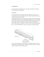
SFP Transceiver
14
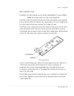
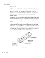
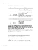
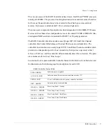
The following table defines the function of each switch:
Each card contains Port Bypass Circuits (PBC) that allows for hot swapping, improved
signal quality and valid FC signal detection. An onboard Clock Recovery Units (CRU) is
provided to improve the signal quality, determine whether the input is a valid FC signal, and
amplification and jitter removal for optimum quality signals.
Cabling diagrams are provided in the Installation chapter for each supported topology. To
ensure proper connectivity, failover and failback operations, and LUN presentation, follow
the cabling diagram for your selected topology.
SFP Transceiver
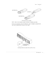
The Host I/O and Disk I/O cards incorporate SFP cages which support optical
hot-swappable Small Form-Factor Pluggable (SFP) transceivers.
The optical SFP transceiver is Class 1 Laser safety compliant and conforms to Class 1 eye
safety standards.
CAUTION:
Do not look into the laser light beam for any extended period of time.
Switch
Name
Function
1
HOST SPEED
Sets the FC Loop speed to 1 Gb or 2 Gb. An LED on the card
will illuminate to indicate 2 Gb mode. The “up” position sets 2
Gb mode and the “down” position will set the loop to 1 Gb
mode.
2
CTRL MODE
Sets the enclosure for a specific controller model. This switch
must be set to the “up” position for the “Wahoo” Controller.
The “down” position is not applicable.
3
HUB FAILOVER
This switch is not used.
4
HOST H0H1 LINK
This switch when enabled, “up” position, provides the link
between the Host I/O card H0 and H1 ports. This switch
should be set to the “down” position when Switch 6 is enabled
(‘up’ position).
5
CTRL0 P0P1 LINK
This switch is not used.
6
DUAL ACTIVE
This switch is enabled (up position) when dual controllers are
installed. It is used to enable automatic internal hub failover
during a controller failure.
7
GND/VCC
This switch is not used.
8
GND/VCC
This switch is not used.
Summary of Contents for OmniStor 4900F Series
Page 1: ......
Page 2: ......
Page 4: ......
Page 38: ...Chapter 1 Getting Started Audible Alarm 24...
Page 58: ...Chapter 2 Topologies and Operating Modes Application of Availability 44...
Page 128: ...Chapter 3 Setup and Installation Powering Off the Storage System 114...
Page 156: ...Chapter 5 Troubleshooting Problems During Bootup 142...
Page 178: ...Chapter 6 Maintenance Replacing the Enclosure 164...
Page 182: ...Appendix A Technical Information Specifications 168...
Page 196: ...Index 182...


