background image

Chapter 3 - Setup and Installation

Multi-Port Mirrored Single Host-Dual Connection Configuration

89

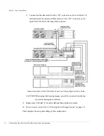
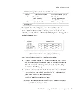
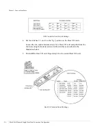
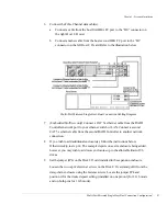
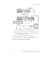
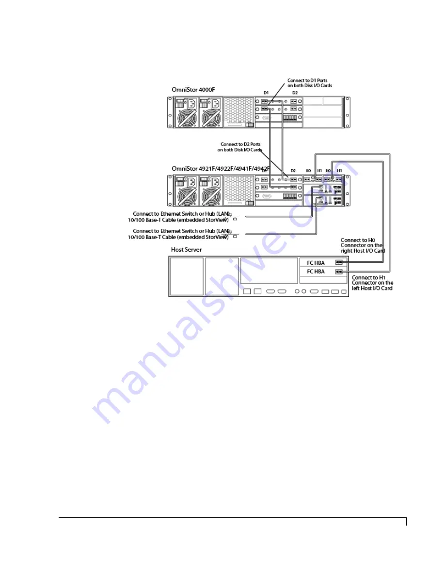
Multi-Port Mirrored Single Host-Dual Connection Cabling Diagram (Daisy-Chain)

CAUTION:

When using dual loop topologies, you will be required to install and 

use volume management software. 

13

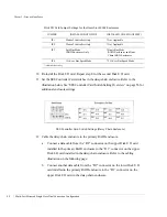
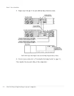
Repeat steps 8 through 11 for each additional daisy-chained enclosure.

14

Power on your system, refer to “Powering On the Storage System” on page 113.

This completes the setup and cabling of this configuration.

Summary of Contents for OmniStor 4900F Series

Page 1: ......

Page 2: ......

Page 3: ...ms Inc All Rights Reserved Rackable Systems Inc 1933 Milmont Ave Milpitas CA 95035 http www rackable com Rackable Systems and OmniStor are trademarks of Rackable Systems Inc The names of actual compan...

Page 4: ......

Page 5: ...4 Optional DC Hot Swappable Power Supplies 5 Cooling Fan Module 7 SES Controller Card 9 Drive Device ID Settings 10 Spin Up Settings 11 Disk IO Card 12 Host IO Card 13 SFP Transceiver 14 RAID Controll...

Page 6: ...Mapping 39 Alternate Path Software 40 Fibre Channel Media Types 40 A Word about Clustering 41 Minimizing Downtime for Maximum Data Availability 41 How Available are Clusters 43 Application of Availab...

Page 7: ...nclosure Fan Speed Control 128 Manual Override 129 Setting the Communications Parameters Automatically 130 Updating the Controller Firmware 131 5 Troubleshooting 135 General Enclosure Problems 135 Com...

Page 8: ...Specifications 171 DC Power Supply Connector Pinout 172 RS 232 Service Port 173 OmniStor Communication Cable Specifications 174 10 100Base T Ethernet Port 174 C Regulatory Information 175 Compliance I...

Page 9: ...dule which contains two in line cooling fans and a redundant N 1 power system with dual hot pluggable independent power supplies Hot swappable components allow the storage system to maintain continuou...

Page 10: ...rs dual AC power supplies dual AC power cords SES Card DB9 null modem cable rackmount rail kit and removable cooling fan module Drives are sold separately OmniStor 4921F is a 12 Bay 2 Gbit per second...

Page 11: ...ment 1GB of cache memory battery backup unit four host ports 2 ports per each Host I O Card and two high performance Disk I O Cards It also includes four optical transceivers a RJ 45 ethernet port dua...

Page 12: ...0 interfaces text based TUI and menu based MUI and StorView with a local access license Typographical Conventions The following typographical conventions are used in the user s guide n Menu items are...

Page 13: ...ent includes onboard environmental monitoring n Designed to fit standard 19 inch rack enclosures and a deskside tower n Front panel LEDs provide notifications of system component status and logical an...

Page 14: ...gurations n Support for up to 512 logical drives n Support for RAID levels 0 1 5 10 and 50 n Online capacity expansion allowing reconfiguration without interruptions n Dynamic Drive Addressing where t...

Page 15: ...board monitoring systems The Components section discusses the major enclosure components The Monitoring section describes the enclosure s LEDs and the manner in which normal and abnormal conditions ar...

Page 16: ...a Glance 2 At a Glance The following illustrations show the featured components of the OmniStor 4900F Series Storage System Familiarize yourself with its components prior to installing and using the s...

Page 17: ...the SES controller The SES controller manages the signals to the front panel through a smart interface Power is applied to the front bezel through the interface edge connector where a control circuit...

Page 18: ...power has been applied The front bezels Power On LED will also be illuminated indicating that power has been applied Each power supply also incorporates an amber general Fault LED If the power supply...

Page 19: ...atures to that of the AC Hot Swappable Power Supplies described on the previous page NOTE The DC system must be installed in a restricted access location in accordance with intent of the National Elec...

Page 20: ...ction devices must meet applicable national and local electrical safety codes and be approved for the intended application Power supply overload protection will shut down the power supply when the out...

Page 21: ...ons In the event of a fault condition the front panel Fan Status LED will change from a green state to a solid amber state in the case of a fan failure or to a blinking amber green state in the case o...

Page 22: ...Controller card has a firmware based VT 100 interface which provides an option to manage fan speed This option provides a whisper mode fan operation for noise sensitive environments When enabled defau...

Page 23: ...tus The processors are responsible for reporting environmental and system status to the front bezel LEDs audible alarms SES Monitoring software VT 100 and external monitoring software such as StorView...

Page 24: ...rd face plate are a set of switches These switches will configure the enclosure base Fibre address which configures the disk drives in each drive slot with a device ID as well as drive delay spin up a...

Page 25: ...control the drive spin up functions The switches are directly attached to all of the drive slot start signals Switch 7 controls the Start_1 signal Delay Spin up and switch 8 controls the Start_2 signa...

Page 26: ...of the enclosure adjacent to the cooling fan bay The upper Disk I O card provides the connection to the Loop 0 side of the disk drives and the lower Disk I O card provides the connection to the Loop 1...

Page 27: ...ivity from the host computer s to the Fibre Channel RAID controller ports This hot swappable card is designed to support NCITS T11 Fibre Channel compliant devices at speeds of 1 0625 Gb per sec or 2 1...

Page 28: ...er safety compliant and conforms to Class 1 eye safety standards CAUTION Do not look into the laser light beam for any extended period of time Switch Name Function 1 HOST SPEED Sets the FC Loop speed...

Page 29: ...Refer to the Installation chapter for transceiver installation procedures Dust covers are provided to protect the transceivers optics It is highly recommend that the dust covers be installed when a c...

Page 30: ...or existing and future Fibre Channel topologies In simplex operations the controller operates autonomously In duplex configurations the two controllers operate as a pair In the event one controller fa...

Page 31: ...f the dual fibre loops on each disk drive The controller s host interface also uses QLogic ISP 2312 dual Fibre Channel controllers which provides two independent ports for host connectivity Each port...

Page 32: ...er includes battery control circuitry for a single cell Lithium Ion battery along with a battery pack mating connector The main purpose of battery backup is to maintain the cache memory during brief p...

Page 33: ...e This protects the 1 amp rated connector when for example a partial short exists caused by aa component failure Lithium Ion batteries have no requirement for conditioning even after partial discharge...

Page 34: ...sues from one operating system to another Also it does not consume any host server CPU cyles or memory with the exception of running the web browser and is truly host OS independent If you have one of...

Page 35: ...complete details Front Bezel LEDs and Reset Button Identification The RAID Controllers provide monitoring data for its environmental condition and logical arrays They communicate that data to the fron...

Page 36: ...r Power Supply Status The Power Supply Status LED indicates the condition of the power supplies The LED will illuminate steady green when both power supplies are functioning normally and will change t...

Page 37: ...alarm will sound when any of the enclosure s component status changes to an abnormal state To silence the alarm press the Alarm Reset button located on the front bezel The corresponding alarm s LED wi...

Page 38: ...Chapter 1 Getting Started Audible Alarm 24...

Page 39: ...42F models with their dual RAID Controllers support the duplex operating mode Operating Mode Overview These operating modes allow you to configure the enclosure s drives and Wahoo RAID Controller s to...

Page 40: ...rt Single Host Dual Connection on page 27 n Dual Port Multi Host Single Connection on page 28 n Dual Port Multi Host Dual Connection on page 29 Dual Port Single Host Connection This topology provides...

Page 41: ...advantages an initially lower cost system to deploy multiple paths from host which can maximize controller bandwidth and it provides multiple paths for optional upstream failover It has several disad...

Page 42: ...he single fibre loop are single points of failure for clustering operations third party clustering software is required and it also has limited bandwidth performance due to a singe Fibre loop 200 MB s...

Page 43: ...he single fibre loop are single points of failure for clustering operations third party clustering software is required and it also has limited bandwidth performance due to a singe Fibre loop 200 MB s...

Page 44: ...oming Fibre loops together so that the surviving controller immediately starts processing host commands There are essentially five supported topologies available for the Duplex mode n Multi Port Mirro...

Page 45: ...transparent failover and failback operations It has several disadvantages performance limited bandwidth capabilities due to the single Fibre loop and the host system host HBA and the single fibre loop...

Page 46: ...erations Logical Drive LUN isolation LUNs appear only once to the host OS and dual connections for higher performance independent access to assigned logical drive It has two disadvantages which are th...

Page 47: ...r failure is detected and also controls the logical function of switch 4 When a controller failure is detected the logic circuit will close connecting the H0 and H1 ports on the Host I O card regardle...

Page 48: ...ogical drives LUNs redundant active active Wahoo2 RAID Controllers transparent failover and failback and shared storage between two host systems Its disadvantage is the single fibre loop which becomes...

Page 49: ...gical drives LUNs redundant active active Wahoo2 RAID Controllers transparent failover and failback and shared storage between two host systems Its disadvantages are the requirement for dual ported HB...

Page 50: ...ared storage and a lower cost to deploy then the multiple switch configuration Its disadvantages are a SAN heterogeneous environment software or volume management for homogenous environment software t...

Page 51: ...o single point of failure when using clustering and path failover software and it provides shared storage Its disadvantages are the requirement for third party failover software when upstream path fai...

Page 52: ...Systems up to the limit of 96 disk drives The JBOD enclosure is configured as a Single Bus Dual Loop system where the drive plane is a continuous 12 twelve drive single bus dual loop FC AL configurat...

Page 53: ...drive mappings can be created with a 2 TB per logical drive limitation Online logical drive addition and deletion is supported SAN LUN Mapping allows multiple hosts and operating systems with exclusiv...

Page 54: ...inaccessible the software redirects the data to the secondary disk object through the alternate path preserving the logical drive This redirection is known as path failover The software continuously t...

Page 55: ...ity Beyond clustering fault tolerant systems can provide 99 9999 uptime At the high end continuous processing systems offer virtually 100 uptime Although the increase from 99 5 to 99 99 availability m...

Page 56: ...echnology that can be implemented in a variety of ways The number of nodes supported and type of interconnection used and a number of other features differentiate cluster implementations One area of i...

Page 57: ...ws Architecture Maximum Availability Downtime per Failure Downtime per Year in minutes Continuous Processing 100 00 None 0 Fault Tolerant 99 9999 Cycles 0 5 5 Clusters 99 9 99 999 Seconds to minutes 5...

Page 58: ...Chapter 2 Topologies and Operating Modes Application of Availability 44...

Page 59: ...l ensure a smooth and trouble free installation The installation is divided into two sections The first section describes installing the enclosure s into the rack cabinet or installing the enclosure c...

Page 60: ...plies should be removed prior to installing the enclosure into the rack cabinet The enclosure chassis could be damaged during installation due to the added unbalanced weight of the power supplies 2 Re...

Page 61: ...ils Secure the left and right mounting rail to the vertical members using the screws and nuts provided Attaching the Rails 6 Lift the enclosure into the rack cabinet and align the rear mounting rails...

Page 62: ...tem Enclosure into the Rack Cabinet 48 Attaching the Chassis Ears 8 Re install the power supplies Slide each power supply into its empty bay and ensure it seats completely and the release latch resets...

Page 63: ...ase latch to the right with your thumb while pulling it from the enclosure 4 Remove the tower stand case from its shipping carton and inspect for obvious damage 5 Locate the accessory kit in the tower...

Page 64: ...p and Installation Installing the Storage System into the Tower Stand 50 pan head screws Inserting and Securing the Chassis 11 Re install the cooling fan module Slide it into its open bay and ensure i...

Page 65: ...es a Remove each drive from its anti static protective packaging Inspect for obvious damage b Install each disk drive into a drive slot by aligning the drive carrier rails with the grooves in the driv...

Page 66: ...s on the Disk I O cards and Host I O cards The transceiver can only be installed one way Note the orientation to ensure proper installation NOTE Refer to the illustration on the following page b Push...

Page 67: ...s skip to Cabling the DC Power Supplies on page 54 a Ensure that the orientation is such that when the power cord is inserted the bale will be on top of the cord and will fit over and onto the cord At...

Page 68: ...If you are using the DC Power Supply system refer to the following procedures to properly connect the cables 1 Plug the connector into the power supply it is keyed to install only one way 2 Connect t...

Page 69: ...The next section Operating Mode Configuration and Cabling includes steps and diagrams for setting the SES Controller card switches Host I O card switches and attaching the required Fibre Channel data...

Page 70: ...will assign a new ID Negotiated addressing occurs when a hard address or a previous address does not exist and it will then negotiate the bus for a new device ID The disadvantage of negotiated device...

Page 71: ...el 1 of the RAID Controller This allows for improved performance throughput The table below provides the drive spin up options DL Switch 7 RM Switch 8 Drive Spin up Mode Down Down Drive motor spins up...

Page 72: ...will be instructed at the appropriate time to set the switches as described previously NOTE If you are installing either a OmniStor 4931F 4932F or a OmniStor 4941F 4942F be sure to connect the ethern...

Page 73: ...peed must be set to the same setting between the disk drives and the Disk I O card s and the host system HBAs BIOS setting and the Host I O cards For example if you are using 2 Gb drives the Disk I O...

Page 74: ...p position Loosen the two captive fastener screws for a Host I O card and pull it from the enclosure using the fastener screws Set the switches as described in the illustration on the following page R...

Page 75: ...I O Card and Switch Settings 5 Re install the Host I O card Repeat step 4 for the second Host I O card 6 Connect the Fibre Channel data cable s a Connect a data cable from the host HBA FC port to the...

Page 76: ...s Locate the jumper JP4 and position it for the desired speed setting installed on one pin only for 2 Gb mode and on both pins for 1 Gb mode 10 Re install the Disk I O card Repeat step 8 for the secon...

Page 77: ...chain enclosure Refer to the cabling illustration below b Connect another data cable from the D2 connector on the upper Disk I O card installed in the primary RAID enclosure to the D1 connector on th...

Page 78: ...for the desired speed setting installed on one pin only for 2 Gb mode and on both pins for 1 Gb mode Disk I O Card 2 Re install the Disk I O card Repeat this step for the second Disk I O card Disk I O...

Page 79: ...en the two captive fastener screws for a Host I O card and pull it from the enclosure using the fastener screws Set the switches as described in the illustration below Refer to the Host I O Card on pa...

Page 80: ...able from the RAID Controller network port to your ethernet switch or LAN 8 If you wish to add additional enclosure s follow the instructions below Otherwise skip to step 14 The example depicts one ex...

Page 81: ...d installed in the primary RAID enclosure to the D1 connector on the upper Disk I O card installed in the daisy chain enclosure Refer to the cabling illustration on the following page b Connect anothe...

Page 82: ...abling Diagram Daisy Chain Enclosure CAUTION When using dual loop topologies you will be required to install and use volume management software 13 Repeat steps 8 through 11 for each additional daisy c...

Page 83: ...for the desired speed setting installed on one pin only for 2 Gb mode and on both pins for 1 Gb mode Disk I O Card 2 Re install the Disk I O card Repeat step 1 for the second Disk I O card Disk I O C...

Page 84: ...her available settings SES Controller Card Switch Settings 4 Set the switches 1 2 and 4 to the Up position on the Host I O cards Loosen the two captive fastener screws for a Host I O card and pull it...

Page 85: ...rnet cable from the RAID Controller network port to your ethernet switch or LAN 8 If you wish to add additional enclosure s follow the instructions below Otherwise skip to step 14 The example depicts...

Page 86: ...d installed in the primary RAID enclosure to the D1 connector on the upper Disk I O card installed in the daisy chain enclosure Refer to the cabling illustration on the following page b Connect anothe...

Page 87: ...ion Cabling Diagram Daisy Chain CAUTION When using dual loop topologies you will be required to install and use volume management software 13 Repeat steps 8 through 11 for each additional daisy chaine...

Page 88: ...or the desired speed setting installed on one pin only for 2 Gb mode and on both pins for 1 Gb mode Disk I O Card 2 Re install the Disk I O card Repeat step 1 for the second Disk I O card Disk I O Car...

Page 89: ...er available settings SES Controller Card Switch Settings 4 Set the switches 1 2 and 4 to the Up position on the Host I O cards Loosen the two captive fastener screws for a Host I O card and pull it f...

Page 90: ...B first HBA FC port to the H1 connector on the left Host I O card d Connect another cable from a second host Node B second HBA FC port to the H1 connector on the right Host I O card Stand Alone Dual P...

Page 91: ...er Card Switch Setting Overview on page 56 for additional enclosure settings SES Controller Card Switch Settings Daisy Chain Enclosure 12 Cable the daisy chain enclosure to the primary RAID enclosure...

Page 92: ...e upper Disk I O card in the daisy chain enclosure Stand Alone Dual Port Dual Host Dual Connection Cabling Diagram Daisy Chain CAUTION When using dual loop topologies you will be required to install a...

Page 93: ...failover and failback During a controller failure internal HUB circuitry located on the Host I O cards automatically connects the incoming Fibre loops together and the surviving controller immediately...

Page 94: ...Locate the jumper JP4 and position it for the desired speed setting installed on one pin only for 2 Gb mode and on both pins for 1 Gb mode Disk I O Card Disk I O Card Jumper Settings for the OmniStor...

Page 95: ...Switch Setting Overview on page 56 for the other available settings SES Controller Card Switch Settings 4 Set the switches 1 2 and 6 to the Up position on the Host I O cards Loosen the two captive fa...

Page 96: ...al enclosure s follow the instructions below Otherwise skip to step 14 The example depicts one extra enclosure being added however you may wish to add more enclosures up to the allowable limit of 96 d...

Page 97: ...closure to the D1 connector on the upper Disk I O card installed in the daisy chain enclosure Refer to the cabling illustration on the following page b Connect another data cable from the D2 connector...

Page 98: ...guration 84 13 Repeat steps 8 through 11 for each additional daisy chained enclosure Multi Port Single Host Single Connection Cabling Diagram Daisy Chain 14 Power on your system refer to Powering On t...

Page 99: ...O Card 2 Re install the Disk I O card Repeat step 1 for the second Disk I O card 3 Locate the switches on the SES Controller card and set them as indicated in the illustration on the following page R...

Page 100: ...e switches 1 2 and 6 to the Up position on the Host I O cards Loosen the two captive fastener screws for a Host I O card and pull it from the enclosure using the fastener screws Set the switches as de...

Page 101: ...rk port to your ethernet switch or LAN Connect a second CAT 5e ethernet cable from the second RAID Controller to another network connection 8 If you wish to add additional enclosure s follow the instr...

Page 102: ...installed in the primary RAID enclosure to the D1 connector on the upper Disk I O card installed in the daisy chain enclosure Refer to the cabling illustration on the following page b Connect another...

Page 103: ...n Cabling Diagram Daisy Chain CAUTION When using dual loop topologies you will be required to install and use volume management software 13 Repeat steps 8 through 11 for each additional daisy chained...

Page 104: ...for the desired speed setting installed on one pin only for 2 Gb mode and on both pins for 1 Gb mode Disk I O Card 2 Re install the Disk I O card Repeat step 1 for the second Disk I O card Disk I O Ca...

Page 105: ...her available settings SES Controller Card Switch Settings 4 Set the switches 1 2 and 6 to the Up position on the Host I O cards Loosen the two captive fastener screws for a Host I O card and pull it...

Page 106: ...o your ethernet switch or LAN Connect a second CAT 5e ethernet cable from the second RAID Controller to another network connection 8 If you wish to add additional enclosure s follow the instructions b...

Page 107: ...installed in the primary RAID enclosure to the D1 connector on the upper Disk I O card installed in the daisy chain enclosure Refer to the cabling illustration on the following page b Connect another...

Page 108: ...l be required to install and use volume management software Multi Port Mirrored Dual Host Single Connection Cabling Diagram Daisy Chain 13 Repeat steps 8 through 11 for each add0itional daisy chained...

Page 109: ...r the desired speed setting installed on one pin only for 2 Gb mode and on both pins for 1 Gb mode Disk I O Card 2 Re install the Disk I O card Repeat step 1 for the second Disk I O card Disk I O Card...

Page 110: ...er available settings SES Controller Card Switch Settings 4 Set the switches 1 2 and 6 to the Up position on the Host I O cards Loosen the two captive fastener screws for a Host I O card and pull it f...

Page 111: ...e left Host I O card c Connect another cable from the second host Node B first HBA FC port to the H1 connector on the left Host I O card d Connect another cable from the second host Node B second HBA...

Page 112: ...or 2 Gb mode and on both pins for 1 Gb mode 10 Re install the Disk I O card Repeat step 8 for the second Disk I O card 11 Set the SES Controller Card switches in the daisy chain enclosure Refer to the...

Page 113: ...ed in the daisy chain enclosure Refer to the cabling illustration on the following page b Connect another data cable from the D2 connector on the lower Disk I O card installed in the primary RAID encl...

Page 114: ...Dual Host Quad Connection Configuration 100 13 Repeat steps 8 through 11 for each additional daisy chained enclosure 14 Power on your system refer to Powering On the Storage System on page 113 This c...

Page 115: ...the desired speed setting installed on one pin only for 2 Gb mode and on both pins for 1 Gb mode Disk I O Card 2 Re install the Disk I O card Repeat step 1 for the second Disk I O card Disk I O Card...

Page 116: ...her available settings SES Controller Card Switch Settings 4 Set the switch 1 2 and 6 to the Up position on the Host I O cards Loosen the two captive fastener screws for a Host I O card and pull it fr...

Page 117: ...nnector on the right Host I O card c Connect a data cable from another switch port to the H0 connector on the left Host I O card Multi Port Mirrored SAN Attach Single Switch Connection Cabling Diagram...

Page 118: ...only for 2 Gb mode and on both pins for 1 Gb mode 10 Re install the Disk I O card Repeat step 8 for the second Disk I O card 11 Set the SES Controller Card switches in the daisy chain enclosure Refer...

Page 119: ...D1 connector on the upper Disk I O card installed in the daisy chain enclosure Refer to the cabling illustration on the following page b Connect another data cable from the D2 connector on the lower...

Page 120: ...hen using dual loop topologies you will be required to install and use volume management software 13 Repeat steps 8 through 11 for each additional daisy chained enclosure 14 Power on your system refer...

Page 121: ...he desired speed setting installed on one pin only for 2 Gb mode and on both pins for 1 Gb mode Disk I O Card 2 Re install the Disk I O card Repeat step 1 for the second Disk I O card Disk I O Card Ju...

Page 122: ...er available settings SES Controller Card Switch Settings 4 Set the switch 1 2 and 6 to the Up position on the Host I O cards Loosen the two captive fastener screws for a Host I O card and pull it fro...

Page 123: ...h port to the H0 connector on the right Host I O card c Connect a data cable from another switch port to the H1 connector on the right Host I O card d Connect a data cable from another switch port to...

Page 124: ...from the daisy chain enclosure using the fastener screws Locate the jumper JP4 and position it for the desired speed setting installed on one pin only for 2 Gb mode and on both pins for 1 Gb mode 10 R...

Page 125: ...the primary RAID enclosure to the D1 connector on the upper Disk I O card installed in the daisy chain enclosure Refer to the cabling illustration on the following page b Connect another data cable fr...

Page 126: ...you with this ability to meet your expanding data storage requirements The Wahoo2 RAID controllers support a feature know as drive roaming where the controllers can keep track of which drive belong to...

Page 127: ...er supply switch to its On position Repeat this step for each of the attached storage system enclosure s All enclosures will perform a power on self test during their initial start 3 Next power on the...

Page 128: ...Chapter 3 Setup and Installation Powering Off the Storage System 114...

Page 129: ...ther the Menu based or Text based VT 100 interface configuration program Refer to the appropriate VT 100 software guide You should monitor your storage system regularly to ensure that the disk drives...

Page 130: ...Status LED indicates the condition of the power supplies The LED will illuminate steady green when both power supplies are functioning normally and will change to amber if one of the power supplies s...

Page 131: ...Configuration Display on page 121 for more information Front Bezel LED Identification Drive Status LEDs There are twelve Drive Status LEDs The Drive Status LED is the left LED of each pair of Drive LE...

Page 132: ...nt bezel Drive LEDs that is drive activity information and drive fault failure or data rebuilding notifications when the front bezel is removed Drive Carrier LitePipes Audible Alarm An audible alarm w...

Page 133: ...Front Bezel LEDs Refer to the table below for a description of the LED conditions and their meaning Front Bezel LED Audible Alarm Matrix Condition Drive Status LED Channel Status LED Audible Alarm Pow...

Page 134: ...reen Steady Amber N A Global Spare Ready Not assigned to a specific Array Fast Blinking Green N A N A Global Spare Rebuilding Blinking Amber Green Steady Amber Continuous Beep Array Failure Failed Dri...

Page 135: ...tings the fan speed control setting Host I O card and Disk I O card bus speed modes presence of Disk I O cards Host I O cards and RAID controllers By pressing and holding the Alarm Reset button the Dr...

Page 136: ...am 1 Connect one end of the null modem serial cable to the RS 232 Service port located on the SES Controller card RS 232 Service Port Connection NOTE The cable is a female to female DB 9 null modem se...

Page 137: ...al components such as disk drives in a specific slot temperature of the thermal sensors cooling fan status power supply status and statistics on enclosure up time Enclosure Environment Status Screen N...

Page 138: ...oth SES processors The interface allows the user to scroll back through the buffer data or select the Transfer Capture Text to save the buffer captures to a text file SES Commands Debug Screen NOTE Op...

Page 139: ...nnection NOTE The cable is a female to female DB 9 null modem serial cable and is included with the storage system Refer to Null Modem Cable Specifications on page 171 for cable specifications 2 Conne...

Page 140: ...ty Screen 6 Select option 5 Firmware Upload by pressing the 5 key Upload Firmware Screen 7 Press the u key lower case to start the upload Using the mouse click on the pull down menu Transfers and sele...

Page 141: ...een completed The upload does not overwrite the firmware during the upload process it writes the new code into unused EEPROM space until completed then erases the flash and re programs the new firmwar...

Page 142: ...for more efficient management of the cooling fans and a whisper mode fan operation for noise sensitive environments where it significantly reduces the noise created by the cooling fans running consta...

Page 143: ...sensor fails or a SES processor fails Manual Override A manual override of the fan speed control is available for special circumstance environments Referring to the illustration on the following page...

Page 144: ...ontroller card Enclosure Terminal Utility at 9 600 BAUD and switch connections to the RAID controller menu based or text based program which uses 115 200 BAUD If this situation occurs you can have the...

Page 145: ...Service port located on the RAID Controller The cable is included with the storage system RS 232 Service Port Connection 2 Connect the other end of the cable with the DB 9 connector to either a host s...

Page 146: ...nu system does not automatically appear after the controller has completed its boot cycle at the screen cursor type Control E Then type Control W to switch the interface to the menu based mode 6 From...

Page 147: ...ers will be displayed 10 When the C s appear click the Transfer pull down menu selection and choose Send File Then select the 1K Xmodem or Xmodem protocol The 1K Xmodem choice is recommended 11 Click...

Page 148: ...ring the upload process it writes the new code into RAM until completed then copies the new firmware code to the EEPROM after verification If you elect to stop a download in progress ensure that the s...

Page 149: ...cord is properly connected to the power module AC PSU If the enclosure is plugged into a three hole grounded outlet verify that power to the outlet has not been interrupted This can be accomplished by...

Page 150: ...If the enclosure is not responding contact your service provider Symptom Reason Solution Host I O Card H0 or H1 Link LED not illuminated Bus speed mode setting not in agreement 1 Verify that Both Host...

Page 151: ...s Disk I O Card D1 or D2 Link LED is not illuminated Bus speed mode setting not in agreement 1 Verify that Both Disk I O Cards jumpers JP4 are set to 2 Gb or 1 Gb mode Both cards must match If there i...

Page 152: ...ta cable is a known good cable Replace the Fibre Channel data cable Verify that all the disk drives are functioning properly Verify that the Host I O Card or Disk I O Card is functioning properly Refe...

Page 153: ...n Status LED is flashing amber Enclosure cabinet over temperature condition Check for obstructed air flow Ensure that the air flow intake at the front bezel is not obstructed and the exhaust air flow...

Page 154: ...e user s guide 2 Power down the enclosure 3 For Hyper Terminal a Select the File menu and choose Properties b Click the Configure button c Choose 9600 and click OK Nothing is displayed on the terminal...

Page 155: ...roller to correct the problem One of the POST diagnostic tests failed Replace the faulty controller The system hangs during a drive scan Follow these steps to resolve the problem 1 Check the enclosure...

Page 156: ...Chapter 5 Troubleshooting Problems During Bootup 142...

Page 157: ...rocedures to replace individual components as well as the entire storage system enclosure Removing the Front Bezel 1 Using a Phillips screwdriver unlock the two front bezel fasteners Unlocking the Fro...

Page 158: ...Chapter 6 Maintenance Removing the Front Bezel 144 2 Grasp and pull the front bezel from the enclosure Refer to the illustration below Removing the Front Bezel...

Page 159: ...ded periods of time greater than five 5 minutes with the cooling fan module removed No cooling is available while the fan module is removed 1 The cooling fan module is located at the rear of the enclo...

Page 160: ...gn the cooling fan module with the opening fan bay and push the module into the enclosure until it completely seats The latch will reset when the module is completely seated The front bezel Fan Status...

Page 161: ...e The storage system will continue to function normally with one power supply during replacement 1 Turn the On Off switch to the Off position on the affected power supply 2 Disconnect the AC power cor...

Page 162: ...er supply by sliding it into its open bay and ensuring it seats completely and the release latch resets 6 Re connect the AC power cord Insert the power cord into the AC power cord module and secure it...

Page 163: ...torage system will continue to function normally with one power supply during replacement 1 Turn the On Off switch to the Off position on the affected power supply 2 Disconnect the DC power cable Sque...

Page 164: ...y sliding it into its open bay and ensuring it seats completely and the release latch resets 6 Re connect the DC power cable Insert the power cable connector into the DC power cable module It secures...

Page 165: ...enclosure or the host computer system The drives are hot swappable Be careful of the P factor effect when removing a disk drive which is the twisting of the drive in your hand as a result of the spin...

Page 166: ...l 5 Install the replacement disk drive a Align the drive carrier with the rail grooves in the drive bay b Ensure that the drive seats completely The drive carrier tension clips ensure that the disk dr...

Page 167: ...e model you have 4 Using the ejector release the transceiver and pull it from the SFP cage a The type A model uses a pivoting mechanism Use the edge of your finger tip or the finger nail to engage the...

Page 168: ...card from the enclosure 8 Note the position of the jumpers on the faulty card 9 Remove the new replacement card from the shipping container and inspect for obvious damage Save the packaging materials...

Page 169: ...completely seats The transceiver protrudes approximately 1 2 inch from the Disk I O card face plate when it s completely seated 13 Remove the dust covers just prior to inserting the FC data cables St...

Page 170: ...illustration below and note the model you have 4 Using the ejector release the transceiver and pull it from the SFP cage a The type A model uses a pivoting mechanism Use the edge of your finger tip or...

Page 171: ...being replaced 10 Insert the replacement card by aligning it into the rail guides and push the card until it fully seats Tighten the captive fastener screw Do not overtighten the screw 11 Insert the t...

Page 172: ...ng the Host I O Card 158 safe place 13 Re connect the Fibre Channel data cables to the replacement card 14 Using the packaging materials from the replacement card repackage the failed card and return...

Page 173: ...astener screws gently pull the card from the enclosure 5 Remove the new replacement card from the shipping container and inspect for obvious damage Save the packaging materials SES Controller Card Swi...

Page 174: ...ller Controller 0 is the lower controller and Controller 1 is the upper controller Removing the RAID Controller 2 Loosen the captive fastener screw on the left side that secures the controller 3 Remov...

Page 175: ...Dual Active Mode The replacement controller will communicate with the disk drives and operating controller and automatically configure its parameters to match its partner controller NOTE Dual Active c...

Page 176: ...ring Off the Storage System on page 113 for the enclosure NOTE Mark or make a notation of the location of the data cables prior to disconnecting or removing these items To facilitate correct installat...

Page 177: ...ion procedures in Chapter 3 Installing the Storage System into the Tower Stand on page 49 11 Re install the SES Controller card Disk I O cards and Host I O cards 12 Re install the power supplies 13 Re...

Page 178: ...Chapter 6 Maintenance Replacing the Enclosure 164...

Page 179: ...r Requirements Power Factor Corrected Input Voltage 48 to 72 VDC Power Requirements 36 to 72 VDC Current per input 48 to 72 VDC Dimensions Rack Mount Unit HxWxD Dimensions Tower Unit HxWxD 3 47 x 17 6...

Page 180: ...agnetic Emissions Requirements EMI FCC Part 15 Class A CISPR 22 EN55022 A VCCI BSMI D33336 C TICK Safety Requirements in compliance with CAN CSA C22 2 60950 00 UL 60950 3rd Edition CB IEC 60950 Editio...

Page 181: ...Supports up to 64 local or global hot spare drives Dynamic Drive Addressing flexible soft addressing Variable stripe size per controller Drive Roaming during power off Automatic error recovery Automat...

Page 182: ...Appendix A Technical Information Specifications 168...

Page 183: ...st IO cards and Disk IO cards Optical SFP Transceiver The Host IO cards and Disk IO cards use a hot swappable Small Form Factor Pluggable SFP transceiver The SFP optical transceiver provides operation...

Page 184: ...rotect the transceivers optics We highly recommend using the dust covers provided SES Controller Card RS 232 Service Port Located below the Disk IO cards at the rear of the enclosure is the SES Contro...

Page 185: ...ns 171 Null Modem Cable Specifications This cable is used to connect a terminal to the SES Controller card RS 232 Service port It is a DB 9 female to DB 9 female null modem type Below is a pin out of...

Page 186: ...ed 48VDC range damage might occur to the unit A DC power cable is included with the 48VDC Power Supplies and is used to connect to a DC power feed system NOTE Use only the DC power cables provided wit...

Page 187: ...ram The VT 100 interface to the firmware program provides access to the configuration utility firmware updates utility and maintenance and monitoring program Below are the pin signals for this connect...

Page 188: ...gned cable used to connect a terminal or host system COM port with a DB 9 connector to the RAID Controller s USB type connector RS 232 Service port Below is the pin out of the cable OmniStor Communica...

Page 189: ...ion in conformity with the Title 47 of the US Code of Federal Regulations Part 15 covering Class A personal computers and peripherals Operation is subject to the following two conditions 1 This device...

Page 190: ...the user will be required to correct the interference at his own expense Rackable Systems Inc is not responsible for any interference caused by unauthorized modifications to this equipment It is the u...

Page 191: ...e Statement Class A Japanese Statement CE Notice Marking by the CE symbol indicates compliance of the device to directives of the European Community A Declaration of Conformity in accordance with the...

Page 192: ...a molded on tandem blade grounding type attachment plug rated 15A 250V configuration 6 15P at the other end For 230 Volt Operation Europe Use a cord set marked HAR consisting of a H05VV F cord that ha...

Page 193: ...ulti Port Mirrored Dual Host Single Connect 90 Multi Port Mirrored SAN Attach Dual Switch 107 Multi Port Mirrored SAN Attach Single Switch 101 Multi Port Mirrored Single Host Dual HBA 85 Multi Port Mi...

Page 194: ...nstalling Transceivers 53 Interface Transfer Rate 166 Interpreting the LEDs 138 J Japanese Statement Class A 177 JBOD Single Bus Dual Loop 38 L LED Channel Status 116 Fan Status 22 116 Power Supply St...

Page 195: ...ring the Chassis Tower 50 Service Port 173 SES Card Firmware 125 SES Commands Debug 124 SES Controller Card 9 Replacing 159 SES Controller Card Switch Settings 56 SES Controller Card Switches 10 Setti...

Page 196: ...Index 182...
Reviews: