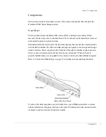


Chapter 1 - Getting Started
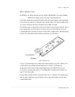
RAID Controllers
17
The core processor of the RAID Controller is based on an Intel XScale™ RISC processor
running at 600 MHz. The processor has integrated instructions and data caches that allow
for the most frequent instructions to be executed without having to access external
memory. It processes commands and I/O’s at extremely high rates.
The processor’s companion chip implements dual independent 64-bit 66MHz PCI busses.
Devices on these busses have independent access to the shared 512 MB of SDRAM. Also,
an integrated XOR accelerator is included for RAID 5 or 50 parity generation.
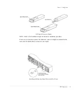
The RAID Controller disk drive interface uses QLogic ISP 2312 dual Fibre Channel
controllers which takes full advantage of the dual fibre loops on each disk drive. The
controller’s host interface also uses QLogic ISP 2312 dual Fibre Channel controllers which
provides two independent ports for host connectivity. Each port can operate at either 1
Gb/sec or 2 Gb/sec, and the controller will automatically detect the correct rate. The ports
are sometimes referred to as “Host Loops.”
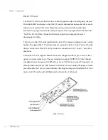
Located on the face plate are RAID Controller Status LEDs. Refer to the table below and
the illustration on the following page for descriptions for each LED.
RAID Controller Status LEDs
PWR - GREEN
Indicates power is applied.
OVR CUR - RED
Indicates controller over current condition e5V.
PRTNR - RED
If on, it will indicate that the partner controller has failed.
DRT - AMBER
Indicates a dirty cache condition.
H0A/H1A - AMBER
Host Loop 0 and 1 Activity.
D0A/D1A - AMBER
Drive Loop 0 and 1 Activity.
H0L/H1L - GREEN
Host Loop 0 and 1 Link Status
D0L/D1L - GREEN
Drive Loop 0 and 1 Link Status
Summary of Contents for OmniStor 4900F Series
Page 1: ......
Page 2: ......
Page 4: ......
Page 38: ...Chapter 1 Getting Started Audible Alarm 24...
Page 58: ...Chapter 2 Topologies and Operating Modes Application of Availability 44...
Page 128: ...Chapter 3 Setup and Installation Powering Off the Storage System 114...
Page 156: ...Chapter 5 Troubleshooting Problems During Bootup 142...
Page 178: ...Chapter 6 Maintenance Replacing the Enclosure 164...
Page 182: ...Appendix A Technical Information Specifications 168...
Page 196: ...Index 182...