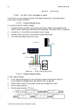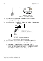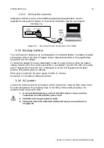
38
CAPTAIN 8
Hunter-Pro Series & Captain 8 Installation Guide
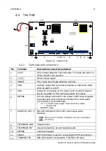
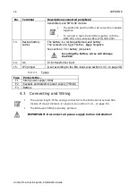
No. Terminal
Description/connected peripheral
transmitters and SMS-100 module.
The GSM-200 and the SMS-100 cannot be installed
together!
To connect a radio transmitter together with the
GSM-200, use a special cable (P/N 3411058).
13.
Backup battery
cables
The battery is a rechargeable lead-acid battery.
The contacts are: Red: Positive; Black: Negative.
See section 2.3 for battery jump-start.
Inverting the battery wires will damage
the PCB!
14.
AC
13.8v transformer input
15.
JP3 jumper
Is set according to the EOL loops (see section 4.3.3, on page 40)
4.2.1.1
Fuses
Fuse Protects the...
F1
Siren power supply (0.9A)
F2
Keypads and detectors power supply (750mA)
F3
Battery
4.3
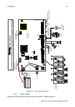
Connecting and Wiring
The overall length of the wirings connected to the BUS cannot exceed 500
meters. If longer distance is required, see section
The BUS uses PIMA proprietary protocol.
IMPORTANT! Disconnect all power supply before installation!
Summary of Contents for Hunter-Pro 8144
Page 111: ...Appendix D CAPTAIN 8 Factory Defaults 111 Hunter Pro Series Captain 8 Installation Guide...
Page 112: ...Appendix D CAPTAIN 8 Factory Defaults 112 Hunter Pro Series Captain 8 Installation Guide...
Page 113: ...Appendix D CAPTAIN 8 Factory Defaults 113 Hunter Pro Series Captain 8 Installation Guide...
Page 114: ...Appendix D CAPTAIN 8 Factory Defaults 114 Hunter Pro Series Captain 8 Installation Guide...
Page 115: ...Appendix D CAPTAIN 8 Factory Defaults 115 Hunter Pro Series Captain 8 Installation Guide...


