34
HUNTER-PRO Series
Hunter-Pro Series & Captain 8 Installation Guide
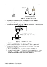
Diagram 30.
TRV/TRU-100 mounting holes
3.
Connect the antenna to the transmitter. Verify that the antenna is straightened.
4.
Verify that the supplied 5 wire cable is firmly attached to the transmitter’s Molex
terminal (labeled “To the system”).
5.
Connect the other end of the cable to the “TRANSMITTER” connector on the control panel.
Diagram 31.
Connecting the TRV/TRU-100
3.12.2
Transmitting in the second frequency
1.
Connect one end of the supplied 2 wire cable to the transmitter’s F2 Molex socket.
2.
Connect the other end of the cable to the control panel, depending on the desired
transmitter mode of operation:
a.
To transmit only in the second frequency, connect the cable to GND (-);
b.
To use the channel on specific event types (e.g. Special Burglary 1 alarms), connect
the trigger wire between F2 and an output terminal on the control panel and set a
proper output type to trigger it (see section 6.10.2, on page 68).
GSM-200
TRV/TRU-100
Control panel case’s top side
TRV/TRU-100
Control Panel
To the
System
F2 Program
TRANSMITTER
Second channel triggering wire.
Connect it to (-) or to a triggering output
1
Summary of Contents for Hunter-Pro 8144
Page 111: ...Appendix D CAPTAIN 8 Factory Defaults 111 Hunter Pro Series Captain 8 Installation Guide...
Page 112: ...Appendix D CAPTAIN 8 Factory Defaults 112 Hunter Pro Series Captain 8 Installation Guide...
Page 113: ...Appendix D CAPTAIN 8 Factory Defaults 113 Hunter Pro Series Captain 8 Installation Guide...
Page 114: ...Appendix D CAPTAIN 8 Factory Defaults 114 Hunter Pro Series Captain 8 Installation Guide...
Page 115: ...Appendix D CAPTAIN 8 Factory Defaults 115 Hunter Pro Series Captain 8 Installation Guide...


