


Programming Your Application
6-15
650S AC Drive
MMI Parameters Table
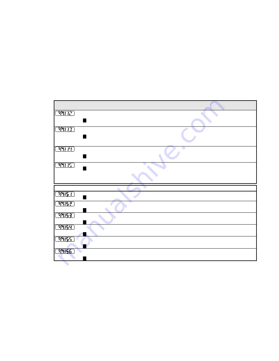
Display
Parameter
Description
Range
Default
THERMAL TIME CST
MOTOR1
M
This parameter is used for the motor1 protection, e.g. I2T motor load. It
defines the thermal time constant of the motor1 that is used to protect
the motor1 against overheating.
Refer to the PMAC MOT PROTECT for a definition.
0 to 10000 s
62s
CUR LOOP BWDTH
MOTOR1
M
Set the current loop bandwidth in Hz. This value will automatically
generate the proportional gain of the PI corrector of the current loop.
The proportional gain is calculated based on the ‘L’ motor 2 parameter.
Modifying this value could induce instability. Please contact Parker SSD
Drives if you need to change it.
10 to 1500 Hz
400Hz
INTEGRAL FREQ
MOTOR1
M
Set the frequency of the I term of the PI current loop corrector. The ratio
CUR LOOP BWDTH/INTEGRAL FREQ must be kept higher than 3.
Modifying this value could induce instability. Please contact Parker SSD
Drives if you need to change it.
1 to 600 Hz
100Hz
SELECT MOTOR1
M
Used to select the motor to run:
0 = motor 2 is selected, e.g. SV Motor Data 2 and SV Motor Ctrl 2
parameters are used by the drive
1 = motor 1 is selected, e.g. SV Motor Data 1 and SV Motor Ctrl 1
parameters are used by the drive
1
SET::PAC2 Menu
MAX SPEED MOTOR2
M
Set the maximum motor 2 speed.
0 to 30000 RPM
4000RPM
MA X CURRENT
MOTOR2
M
Set the motor 2 maximum current in Amps rms.
1.0 to 512.0 Arms
10.6A
PERM CURRENT
MOTOR2
M
Set the motor 2 nominal current in Amps rms.
1.0 to 512.0 Arms
5.24A
PERM TORQUE
MOTOR2
M
Set the motor 2 nominal torque in Nm.
1.0 to 512.0 Nm
5.5Nm
POLES
MOTOR2
M
Set the motor 2 number of poles.
0 to 400
10
BACK EMF
MOTOR2
M
Set the motor2’s Back EMF phase to phase, rms value (in
Volts/1000RPM)
0 to 8192
Vrms/1000RPM
65.5V


