Parker 650S Series Product Manual Download Page 41

5-2  

The Keypad 


650S AC Drive 

The 6511 Keypad 


The 6511 Keypad (Man-Machine Interface, MMI) provides for local control 
of the drive, monitoring, and complete access for application programming. 

The 650S can be fitted with either a Standard or Remote Keypad. Both 
Keypads fit on the front of the drive, but the Remote Keypad (with its extra 
connector) can also be remote-mounted up to 3 metres away using a 
connecting lead: refer to Chapter 3: “Installing the Drive” – Fitting the 
Remote Keypad.  

To remove a Keypad, simply pull it away from the drive. To refit it, push it 
back into place. 

The product rating label identifies the Drive/Keypad type: refer to Chapter 9: 
“Technical Specifications” – Understanding the Product Code. 


The Power-Up Condition 

On initial power-up, direct from the factory, the drive is in Local Control and the MMI will display the Local Setpoint, 

.  

All parameters will be at factory default settings. Any changes to these conditions are automatically saved. The drive will 
initialise on subsequent power-ups with the previously saved settings and control mode, Local or Remote Control. 
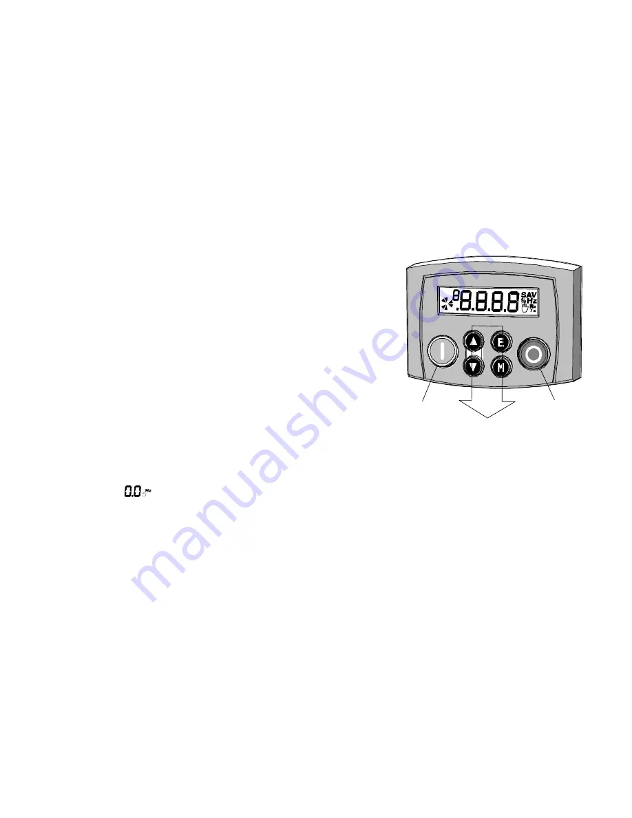
Programming Keys


Local


Key


Control


Local


Key


Control


Summary of Contents for 650S Series

Page 1: ...650S 650S P P Pr r ro o od d du u uc c ct t t M M Ma a an n nu u ua a al l l HA500924U001 S E R I E S ...

Page 2: ...thout notice to make amendments or correct omissions Parker SSD Drives cannot accept responsibility for damage injury or expenses resulting therefrom WARRANTY Parker SSD Drives warrants the goods against defects in design materials and workmanship for the period of 24 months from the date of manufacture or 12 months from the date of delivery whichever is the longer period on the terms detailed in ...

Page 3: ... all performance endurance maintenance safety and warning requirements of the application are met The user must analyze all aspects of the application follow applicable industry standards and follow the information concerning the product in the current product catalog and in any other materials provided from Parker or its subsidiaries or authorized distributors To the extent that Parker or its sub...

Page 4: ...d and used INSTALLATION DETAILS Model Number see product label Where installed for your own information Unit used as a refer to Certification ο Component ο Relevant Apparatus Unit fitted Enclosure Application Area The equipment described is intended for industrial motor speed control utilising AC synchronous permanent magnet machines Personnel Installation operation and maintenance of the equipmen...

Page 5: ... drive 4 There may still be dangerous voltages present at power terminals motor output supply input phases DC bus and the brake where fitted when the motor is at standstill or is stopped 5 For measurements use only a meter to IEC 61010 CAT III or higher Always begin using the highest range CAT I and CAT II meters must not be used on this product 6 Allow at least 10 minutes for the drive s capacito...

Page 6: ... Ensure all external wiring is rated for the highest system voltage Thermal sensors contained within the motor must have at least basic insulation All exposed metalwork in the Drive is protected by basic insulation and bonded to a safety earth RCDs are not recommended for use with this product but where their use is mandatory only Type B RCDs should be used EMC In a domestic environment this produ...

Page 7: ...MENT Under fault conditions power loss or unintended operating conditions the drive may not operate as intended In particular Stored energy might not discharge to safe levels as quickly as suggested and can still be present even though the drive appears to be switched off The motor s direction of rotation might not be controlled The motor speed might not be controlled The motor might be energised ...

Page 8: ... 9 8 Cabling Requirements for EMC Compliance 9 9 Internal Dynamic Braking Circuit 9 10 External Brake Resistor 9 11 Supply Harmonic Analysis 230V filtered 9 13 Supply Harmonic Analysis 400V filtered 9 14 Supply Harmonic Analysis 230V unfiltered 9 15 Supply Harmonic Analysis 400V unfiltered 9 16 Chapter 10 Certification for the Drive 10 1 Requirements for EMC Compliance 10 2 Earthing Requirements 1...

Page 9: ...Cont 8 ...

Page 10: ...Getting Started 1 1 650S AC Drive Chapter 1 Getting Started Introduction to the 650S Series AC Drive Introduction 1 2 Equipment Inspection 1 3 Storage and Packaging 1 3 About this Manual 1 3 ...

Page 11: ...ures Local or Remote mode operation SELV control terminals Safe Extra Low Volts Intelligent monitoring strategy to avoid nuisance tripping In built protection of the unit against overloads excessive voltages phase to phase and phase to earth short circuits An internal RFI filter is fitted as standard An internal dynamic brake switch for connection to an external resistor 400V units only Quiet oper...

Page 12: ...t in transit damage If the unit is not being installed immediately store the unit in a well ventilated place away from high temperatures humidity dust or metal particles About this Manual This manual is intended for use by the installer user and programmer of the drive It assumes a reasonable level of understanding in these three disciplines Note Please read all Safety Information before proceedin...

Page 13: ...1 4 Getting Started 650S AC Drive ...

Page 14: ...Product Overview 2 1 650S AC Drive Chapter 2 Product Overview An overview of the 650S AC Drive Component Identification 2 2 ...

Page 15: ...2 Keypad 3 DIN clip fixing bracket 4 Terminal cover 5 Power terminals 6 Motor cable screen clamp 7 Control terminals 8 Volt free relay contacts 9 Product rating label 10 Motor thermistor terminals 11 RS232 programming port P3 12 Encoder digital inputs Frame 1 Illustrated 11 7 6 5 4 3 ...

Page 16: ...ve 3 1 650S AC Drive Chapter 3 Installing the Drive How to install your drive Mechanical Installation 3 2 Mounting the Drive 3 3 Ventilation 3 3 Electrical Installation 3 4 Wiring Instructions 3 4 Optional Equipment 3 11 ...

Page 17: ...l mounting W 2 H1 H4 H3 C DIN centreline H2 REAR VIEW Frame 3 H1 H3 C DIN centreline W 2 H4 W DIN centreline REAR VIEW Frame 1 illustrated Frame 2 similar Fixing Torque Weight H1 Fixing Centres H2 H3 H4 C W D Frame 1 M4 1 5Nm 0 85kg 2 lbs 132 5 2 143 5 6 35 1 4 139 5 5 6 0 2 73 2 9 142 5 6 Frame 2 M5 3 0Nm 1 4kg 3 lbs 188 7 4 201 7 9 35 1 4 194 7 7 6 5 0 24 73 2 9 173 6 8 Frame 3 M5 3 0Nm 2 7kg 6 ...

Page 18: ...Mounting To DIN mount the unit hang the unit on the top DIN rail and push the unit onto the bottom DIN rail until it snaps in to position Secure with a lower screw fixing To release the unit use a flat bladed screwdriver as shown Ventilation Maintain a minimum air clearance for ventilation of 100mm 4 inches above and below the unit When mounting two or more 650S units together these clearances are...

Page 19: ...ol Wiring This is the simplest installation Every new drive will operate in Local Control when first powered up The keypad is used to start and stop the drive Refer to the Connection Diagram and install the Thermistor cable or link jumper terminals TH1A and TH1B we recommend you do use a thermistor Motor cable Supply cable Follow the earthing grounding and screening advice Refer to Chapter 4 Opera...

Page 20: ...push button starting Referring to the Connection Diagram Follow the instructions for Local Control Wiring as detailed previous Install using minimum connections Note You can still operate the drive in Local mode if necessary with any Application selected Refer to Chapter 4 Operating the Drive and follow the relevant instructions for Single Wire Starting or Push Button Starting WARNING This product...

Page 21: ...1 220 240V ac Frame 2 3 220 240V ac Frame 3 M1 U M2 V M3 W L1 TH1A TH1B L2 N 1 220 240V ac Frame 1 Power Terminal Variations 3 380 460V ac Refer to Chapter 12 Applications for specific control wiring for each Application Frame 2 3 380 460V ac Wiring Instructions IMPORTANT using two independent protective earth ground incoming supply conductors DIN6 ENC A DIN7 ENC B 1 Remove the terminal cover from...

Page 22: ...rable digital input output Not Stop input 0V No latching of Run DIN1 24V Run latched 0 24V Current sourcing 9 DIN3 DOUT1 Configurable digital input output Jog configurable digital input 0V Stop 24V Jog 0 24V 8 DIN2 Direction configurable digital input 0V Forward 24V Reverse 0 24V 7 DIN1 Run Forward configurable digital input 0V Stop 24V Run 0 24V 6 24V 24V supply for digital I O 24V 5 AOUT1 Ramp O...

Page 23: ...220 240V or 380 460V ac 10 rms with respect to L2 L3 phase to phase 50 60Hz IT TN L2 N L2 Power Input Single phase neutral or L2 three phase live connection 220 240V ac 10 with respect to L1 50 60Hz IT TN 220 240V or 380 460V ac 10 with respect to L1 L3 50 60Hz IT TN L3 Power Input Three phase live connection Not applicable 220 240V or 380 460V ac 10 with respect to L1 L2 50 60Hz IT TN DC No user ...

Page 24: ... 0mm2 10 AWG 6 0mm2 10 AWG 2 5mm2 12 AWG Frame 3 400V 6 0mm2 10 AWG 6 0mm2 10 AWG 2 5mm2 12 AWG Power Wiring Note For specified EMC emission and immunity performance install to EMC Installation Instructions Refer to Chapter 10 Certification for the Drive for more information Terminal tightening torque for Frame 3 power connections is 20 lb in 2 26Nm Protect the incoming mains supply using the spec...

Page 25: ...ghest system voltage All control terminals are SELV i e double insulated from power circuits Using Cage Clamp Terminals Strip wire insulation to 5 6mm 0 20 0 24 inches or alternatively use wire crimps Use a flat bladed screwdriver maximum blade size 3 5mm The cage provides the correct force for a secure connection IMPORTANT DO NOT lever or turn the screwdriver ...

Page 26: ...ng the RS232 P3 port located under the terminal cover A standard P3 lead Parker SSD Part Number CM057375U300 which is used to connect the Keypad to the drive Two self tapping screws are provided with the Keypad Remove the protective film from the gasket An enclosure rating of IP20 is achieved for the remote Keypad when correctly mounted Assembly Procedure ...

Page 27: ...ng below can be photocopied actual size 100 and used as a template Additional Remote Keypad Options 650S is also compatible with 6521 6901 6911 Opstations which all require a 6052 Mounting Kit if door marked IP20 The assembly procedure is supplied with the mounting kit ...

Page 28: ... drive s Wiring is very simple all connections are SELV Safe Extra Low Voltage Select to use RS485 or RS232 by wiring to the appropriate terminal on the module Note RS485 and RS232 terminals cannot be used simultaneously We recommend you ground the module to the system earth using the Functional Earth terminal RS485 Connections RS232 Connections master to single multiple slave master to single sla...

Page 29: ... Un Shielded Cable Connections A RxA TxA B RxB TxB Shield Rx Tx Ground 0V Signal Levels To RS485 Standard To RS232 Standard Receiver Input Impedance Unit Load 3 kΩ minimum 7kΩ maximum Maximum Cable Length 1200m 4000ft 3 metres Maximum Baud Rate 57 6kbaud 57 6kbaud Maximum Number of Units 32 including slaves and masters 2 1 master and 1 slave only ...

Page 30: ...drive power or serious hardware fault Rx INTERMITTENT Indicates activity on the receive line carrying data from the Master Tx INTERMITTENT Indicates activity on the transmit line carrying data to the Master Configure the Drive Before the module can be used you must configure the drive to your system Set up the parameters in the SERIAL menu as appropriate Refer to Chapter 6 Programming Your Applica...

Page 31: ...be made in screened cable Use cable with an overall screen and a screen over each individual pair To ensure compliance with the EMC Directive the overall cable screen should be connected to the drive chassis Recommended cable pairs individually screened Belden equivalent 8777 Parker SSD Drives Part Number CM052666 The drive will operate with 5 24V encoders Provide the correct supply for the encode...

Page 32: ... for the first time now learn about the various ways you can start and stop the drive This chapter also offers some application advice Pre Operation Checks 4 2 Initial Start up Routines 4 3 Local Control Operation 4 4 Remote Control Operation 4 5 Set up 4 6 Tuning the Drive to Your System 4 7 ...

Page 33: ...ling fans are intact and free from obstruction Ensure the safety of the complete system before the drive is energised Ensure that rotation of the motor in either direction will not cause damage Ensure that nobody else is working on another part of the system which will be affected by powering up Ensure that other equipment will not be adversely affected by powering up Prepare to energise the drive...

Page 34: ...e can be started in either Remote Control or Local Control By default the drive will start in Local Control These routines assume that the drive s control terminals are wired as shown in the Control Wiring Connections in Chapter 3 Connected in this way a positive setpoint will rotate the motor in a clockwise direction when viewed down the shaft looking toward the motor Note If during the start up ...

Page 35: ...TART T To change the direction to forwards the normal direction press STOP S or START S Note that the Setpoint parameter will not change sign to indicate this change however the rotating indicator on the MMI will show the direction We recommend that you use the STOP key commands if the motor is stopped and the START key commands if the motor is running The keys should be pressed and released toget...

Page 36: ...ive is now complete The drive will operate as a sensorless drive It is programmed to control a PMAC motor of equivalent power current and voltage rating to the drive Using the keypad or other suitable programming tool the drive must now be set up STOP START Close the RUN switch DIN1 RUN SWITCH 0 100 5 POTENTIOMETER STOP START RUN SWITCH Open the RUN switch DIN1 and the motor will ramp to zero Appl...

Page 37: ...e motor s torque constant in Nm Amps rms INERTIA 0 070 Set the motor s inertia The units for this parameter are set by the INERTIA SCALE parameter INERTIA SCALE 0 Set the motor s inertia scale 0 gm 1 kgcm 2 kgm THERMAL TIME CST 62s This parameter is used for the motor protection e g I2T motor load It defines the thermal time constant of the motor that is used to protect the motor1 against overheat...

Page 38: ...e demand T after a time equal to speed int time Tuning the Drive to Your System Finally adjust the parameters below as necessary to tune the drive to your system Refer to Chapter 6 Programming Your Application for details Display Parameter Default Brief Description MAX SPEED Default is Product Code dependent Set the speed in Hz at which the 650S will run when the maximum setpoint is applied MIN SP...

Page 39: ...4 8 Operating the Drive 650S AC Drive ...

Page 40: ...5 3 Control Key Definitions 5 3 Display Indications 5 4 Drive Status Indications 5 5 The DIAGNOSTICS Menu 5 6 The Menu System 5 7 How To Change a Parameter Value 5 8 Special Menu Features 5 9 Resetting to Factory Defaults 2 button reset 5 9 Changing the Drive Operating Frequency 5 9 Selecting Local or Remote Control 5 10 Password Protection 5 11 Selecting the Menu Detail 5 12 ...

Page 41: ...Remote Keypad To remove a Keypad simply pull it away from the drive To refit it push it back into place The product rating label identifies the Drive Keypad type refer to Chapter 9 Technical Specifications Understanding the Product Code The Power Up Condition On initial power up direct from the factory the drive is in Local Control and the MMI will display the Local Setpoint All parameters will be...

Page 42: ...er is adjustable Increment Navigation Move upwards through the menu system Parameter Increase value of the displayed parameter Local Mode Increase value of the local setpoint Decrement Navigation Move down through the menu system Parameter Decrease value of the displayed parameter Local Mode Decrease value of the local setpoint Run Local Mode Run the drive Trip Reset Resets trip condition allowing...

Page 43: ...s for percentage Hz for frequency in Hertz Indicates the drive is in Local control Drive is in remote control when not visible when in the Parameter menu when in the Setup menu when displaying an Alarm code a negative parameter value Sensorless Vector operating mode Indicates control via fieldbus communications Indicates parameter numbers or values trip information error codes etc See Drive Status...

Page 44: ...rms present Added or removed from the display letter by letter to indicate entering or leaving Local Control STOP Coast Stop or Prog Stop active Jog 6901 op station only or Run pressed while Coast Stop or Prog Stop lines are active low on the sequencing block Local control only RUN Not possible to change between Local Remote mode The drive is running in Local mode or the Remote run signal is activ...

Page 45: ...ICS Menu Display Name Description FREQUENCY The current output frequency in Hertz SPEED SETPOINT The set point as a percentage of MAX SPEED DC LINK VOLTS Vac rms x 2 dc link Volts when motor stopped MOTOR CURRENT The current load value in Amps ...

Page 46: ...The Keypad 5 7 650S AC Drive The Menu System The menu system is divided into a tree structure with 3 menu levels ...

Page 47: ...r information View the parameter to be edited and press to display the parameter s value Select the digit to be changed pressing the key moves the cursor from right to left Use the keys to adjust the value Hold the key momentarily to adjust the value marginally or hold the key to make rapid changes the rate of change varies with the time held Press to return to the parameter display The new value ...

Page 48: ... the drive This displays parameter E 0 01 Press the key to navigate to E 0 02 Press the key to edit the parameter 0 50Hz default 1 60Hz Select the required frequency then press the key Power down the drive No permanent change has been made to the drive at this point To save the change to parameter E 0 02 you must now perform a 2 button reset as above Please note that this will return the drive to ...

Page 49: ...ocal Setpoint parameter whose value is adjusted on the MMI Note You can only change between Local and Remote Control when the drive is stopped and either or the Local Setpoint is displayed Remote to Local Control Local to Remote Control Note For safety reasons the drive will not return to Remote Control if this will cause the drive to start Check RUN and JOG inputs are low Hold this key down until...

Page 50: ...1 Go to Press Try to edit any parameter with password activated Go to Press 2 Enter new password using for example Enter current password using for example Enter current password using for example 3 Press repeatedly until top of menu is reached Remote Setpoint or Local Setpoint Press Original parameter displayed password de activated Press Reset to 0000 using 4 Press to activate password Remote Se...

Page 51: ... Refer to Chapter 6 to see how the setting changes the displayed menu Additional parameters are indicated with F in the table Navigate to the parameter SET SETP ST99 and press the key This toggles full or partial menu detail The default setting of 0 provides partial menu detail Set the parameter to 1 for full menu detail ...

Page 52: ...ramming simply involves changing parameter values Programming Your Application 6 2 MMI Parameters 6 2 MMI Parameters Table 6 3 Configuring Terminals 9 10 Digital Input Output 6 30 PID Tuning Your Drive 6 32 Auto Restart 6 33 Minimum Speed Mode 6 34 Product Related Default Values 6 34 Frequency Dependent Parameters 6 35 Power Dependent Parameters 6 36 ...

Page 53: ...the keypad or MMI Man Machine Interface For more information about these and additional parameters accessible using ConfigEd Lite or other suitable programming tool refer to the 650S Software Product Manual on our website www SSDdrives com Key to MMI Parameters Table F Parameters indicated with F are visible with full menus only Refer to the DETAILED MENUS parameter ST 99 M Parameters indicated wi...

Page 54: ...is digital input 1value 0x0002 is digital input 2 value 0x0004 is digital input 3 value 0x0008 is digital input 4 value 0x0010 is digital input 5 value 0x0020 is digital input 6 value 0x0040 is digital input 7 value AIN 1 VALUE The input reading with scaling and offset applied x x AIN 2 VALUE The input reading with scaling and offset applied x x DIAG OUTPUTS Menu DOUT WORD Four digit Hexadecimal n...

Page 55: ...cent trip that caused the drive to stop The value displayed is the Trip ID number that can be found in the table Hexadecimal Representation of Trips chapter 7 0 TRIP6 Records the sixth most recent trip that caused the drive to stop The value displayed is the Trip ID number that can be found in the table Hexadecimal Representation of Trips chapter 7 0 TRIP7 Records the seventh most recent trip that...

Page 56: ... integral time constant of the speed loop A speed error which causes the proportional term to produce a torque demand T will cause the integral term to also ramp up to a torque demand T after a time equal to speed int time 1 to 15000ms product code dependent SPEED POS LIMIT F This sets the upper limit of the speed demand 110 00 to 110 00 110 00 SPEED NEG LIMIT F This sets the lower limit of the sp...

Page 57: ...the signal TRUE or FALSE 0 FALSE 1 TRUE 0 DOUT 2 INVERT Inverts the value of the signal TRUE or FALSE 0 FALSE 1 TRUE 0 RELAY INVERT Inverts the value of the signal TRUE or FALSE 0 FALSE 1 TRUE 0 AOUT 1 SCALE 300 00 to 300 00 100 00 AOUT 1 OFFSET 300 00 to 300 00 0 00 AOUT 1 ABSOLUTE SCALE OFFSET X VALUE ABS X OUTPUT 100 0 CLAMP 0 FALSE not absolute 1 TRUE absolute 1 AOUT 2 SCALE 300 00 to 300 00 1...

Page 58: ... 2 DESTINATION F Same as DIN 1 DESTINATION Same as DIN1 DESTINATION 2 RUN REVERSE DIN 3 DESTINATION F Same as DIN 1 DESTINATION Same as DIN1 DESTINATION 4 JOG DIN 4 DESTINATION F Same as DIN 1 DESTINATION Same as DIN1 DESTINATION 3 NOT STOP DIN 5 DESTINATION F Same as DIN 1 DESTINATION Same as DIN1 DESTINATION 8 NOT COAST STOP DIN 6 DESTINATION F Same as DIN 1 DESTINATION Same as DIN1 DESTINATION ...

Page 59: ...et by P 2 For example if MAX SPEED 50Hz and Setpoint 30Hz then 1 of MAX SPEED 0 5Hz So AT LOAD is True between 30 0 5Hz AT LOAD the magnitude of the output torque is greater than or equal to the torque level set in ST 42 0 NONE 1 HEALTH 2 TRIPPED 3 RUNNING 4 AT ZERO 5 AT SPEED 6 AT LOAD 0 NONE DOUT 2 SOURCE Refer to Configuring Terminals 9 10 Digital Input Output page 6 30 F 0 NONE 1 HEALTH 2 TRIP...

Page 60: ...the dynamic brake switch trip As S LOOP 1 SPEED FEEDBACK Disables the speed feedback trip As S LOOP 0 OVERSPEED Disables the overspeed trip As S LOOP 0 DISPLAY KEYPAD Disables the display keypad trip As S LOOP 0 DC LINK RIPPLE F Disables the DC link ripple trip As S LOOP 0 SET SERL Menu REMOTE COMMS SEL F Selects the type of remote communications mode 0 FALSE and in REMOTE mode then control is fro...

Page 61: ... RS232 programming port on the drive s control board When EIBISYNC ASCII is selected BAUD RATE is 19200 and PARITY is EVEN FIELDBUS is reserved for future use As S SE07 0 SET SETP Menu JOG ACCEL TIME As P 4 for Jog 0 0 to 3000 0s 1 0 JOG DECEL TIME As P 5 for Jog 0 0 to 3000 0s 1 0 RAMP TYPE Selects the ramp type 0 LINEAR 1 S 0 S RAMP JERK Rate of change of acceleration of the curve in units per s...

Page 62: ... to Chapter 7 Trips and Fault Finding Hexadecimal Representation of Trips 0x0000 to 0xFFFF 0x0000 AUTO RESTART TRIGGERS Allows Auto Restart to be enabled for a selection of trip conditions Refer to Chapter 7 Trips and Fault Finding Hexadecimal Representation of Trips 0x0000 to 0xFFFF 0x0000 DB ENABLE Enables operation of the dynamic braking 0 FALSE 1 TRUE 1 DB RESISTANCE The value of the load resi...

Page 63: ...ABLED ENABLED ENABLED ENABLED ENABLED ENABLED ENABLED ENABLED ENABLED 6511 When using the standard 6511 and 6521 keypad disabling the DIR key prevents the local setpoint going negative for reverse Similarly disabling the L R key prevents the drive being changed from Local to Remote or Remote to Local modes APPLICATION LOCK F Setting this parameter to TRUE prevents editing of parameter P 1 Set this...

Page 64: ...ed is measured in revs per second Changing the ENC SPEED SCALE value to 60 00 will provide an output in revs per minute To provide an output in percent of the motor maximum speed where maximum speed is the maximum speed your motor will run in rpm the ENC SPEED SCALE parameter should be set to the result of 6000 maximum speed rpm 0 00 to 300 00 1 00 ENC SPEED F Speed feedback in units defined by th...

Page 65: ...2 0 Nm 2 0Nm POLES MOTOR1 M Set the motor 1 number of poles 0 to 400 10 BACK EMF MOTOR1 M Set the motor1 s Back EMF phase to phase rms value in Volts 1000RPM 0 to 8192 Vrms 1000RPM 50 9V R MOTOR1 M Set the motor1 s resistance between phase at 25 C 0 to 50 Ohms 6 58Ohms L MOTOR1 M Set the motor1 s inductance between phase at nominal current 0 to 1000mH 20 3mH KT MOTOR1 M Set the motor1 s torque con...

Page 66: ...erm of the PI current loop corrector The ratio CUR LOOP BWDTH INTEGRAL FREQ must be kept higher than 3 Modifying this value could induce instability Please contact Parker SSD Drives if you need to change it 1 to 600 Hz 100Hz SELECT MOTOR1 M Used to select the motor to run 0 motor 2 is selected e g SV Motor Data 2 and SV Motor Ctrl 2 parameters are used by the drive 1 motor 1 is selected e g SV Mot...

Page 67: ...r2 protection e g I2T motor load It defines the thermal time constant of the motor1 that is used to protect the motor1 against overheating Refer to the PMAC MOT PROTECT for a definition 0 to 10000 s 76 4s CUR LOOP BWDTH MOTOR2 M Set the current loop bandwidth in Hz This value will automatically generate the proportional gain of the PI corrector of the current loop The proportional gain is calculat...

Page 68: ... of the PI corrector used for extracting speed and position The default value is appropriate for most motors 0 to 2000 1 PI INTEGRAL MOTOR1 Set the Integral frequency of the PI corrector used for extracting speed and position The default value is appropriate for most motors 1 to 2000 Hz 20Hz SPD THRESHOLD MOTOR1 Set the threshold value used to enable disable the I term of the PI corrector used for...

Page 69: ...for most applications The total gain applied is PI GAIN ADAPTATION GAIN With ADAPTATIONGAIN SPDSTARTGRDfrom0toSPDGRD SPDSTARTGRD ADAPTATIONGAIN SPDGRD real_speed RPM fromSPDGRD SPDSTARTGRD toSPDGRD ADAPTATIONGAIN 1aboveSPDGRD 0 1 to 100 5 SPD GRD MOTOR1 The gain of the PI corrector varies as 1 over speed To maintain the PI gain at a constant value over the whole range of the speed the gain is inte...

Page 70: ...hm It defines the speed at which the variation stops The default value is 50 RPM and is considered appropriate for most applications As it is mostly used to start the motor a very low value between 0 to 100RPM must be selected if changed from the default value 32000 to 32000 RPM 50RPM ENABLE STARTUP MOTOR1 Start the motor with a high friction load This parameter is used to enable disable a specifi...

Page 71: ...load The percentage value is a percentage of the nominal motor current I0 of the PMAC MOTOR function block This value cannot be higher than 150 of the drive rating The default value of 10 is considered appropriate for most applications 0 to 200 10 STARTUP SPEED MOTOR1 This parameter is used in conjunction with the ENABLE STARTUP parameter It selects the speed setpoint at which the speed control is...

Page 72: ... PI corrector used for extracting speed and position The default value is appropriate for most motors 0 to 2000 1 PI INTEGRAL MOTOR2 Set the Integral frequency of the PI corrector used for extracting speed and position The default value is appropriate for most motors 1 to 2000 Hz 20Hz SPD THRESHOLD MOTOR2 Set the threshold value used to enable disable the I term of the PI corrector used for extrac...

Page 73: ...opriate for most applications The total gain applied is PI GAIN ADAPTATION GAIN With ADAPTATIONGAIN SPDSTARTGRDfrom0toSPDGRD SPDSTARTGRD ADAPTATIONGAIN SPDGRD real_speed RPM fromSPDGRD SPDSTARTGRD toSPDGRD ADAPTATIONGAIN 1aboveSPDGRD 0 1 to 100 5 SPD GRD MOTOR2 The gain of the PI corrector varies as 1 over speed To maintain the PI gain at a constant value over the whole range of the speed the gain...

Page 74: ... 100RPM must be selected if changed from the default value 32000 to 32000 RPM 50RPM ENABLE STARTUP MOTOR2 Start the motor with a high friction load This parameter is used to enable disable a specific startup procedure when the motor drive is switched ON starting rotation This is mainly used where applications need to start the motor with a high inertia and or friction load and the standard start i...

Page 75: ...mum application speed MAX SPEED of the REFERENCE function block In open loop mode the system is not controlled in speed mode It must only be used to start the motor under heavy conditions or to transitorily reach the zero speed or crossing the zero speed setpoint It is not intended to be used to control accurately a motion 0 to 100 5 SET IPPA Menu AIMING POINT Determines the final level of the inv...

Page 76: ...olarisation mode Clear it for standard SV control mode 0 FALSE 1 TRUE POLAR START Set this parameter to enable the motor polarisation mode Clear it to disable the motor polarisation mode 0 FALSE 1 TRUE MOTOR PHASE Select on which motor phases the motor polarisation is applied When the motor polarisation is enabled changing the motor phase allows to rotate the motor like a stepper motor That gives ...

Page 77: ... point at the end of the move command 0 01 to 1000 00 1 00 REDUCED WINDOW Define the position window length in which the speed set point is reduced 0 00 to 1000 00 0 00 GAIN Set the position loop proportional gain 0 10 to 100 00 10 00 MARK INPUT Specify which digital input is used as the mark input 0 NONE 1 DIN1 2 DIN2 3 DIN3 4 DIN4 5 DIN5 6 DIN6 7 DIN7 0 ACTIVE True if there is an ongoing move 0 ...

Page 78: ...not control a motor APP 6 7 8 are for future use You can edit an Application in DSELite and then set this parameter to CUSTOM to produce your own custom Application Refer to the 650S Software Product Manual Chapter 5 Applications which gives detailed information about each Application Note Parameter values are changed to factory settings by loading a new Application except Motor Parameters indicat...

Page 79: ...00 00 PRESET 1 A user adjustable speed preset 100 00 to 100 00 20 00 PRESET 2 A user adjustable speed preset 100 00 to 100 00 50 00 PRESET 3 A user adjustable speed preset 100 00 to 100 00 100 00 PRESET 4 A user adjustable speed preset 100 00 to 100 00 10 00 PRESET 5 A user adjustable speed preset 100 00 to 100 00 20 00 PRESET 6 A user adjustable speed preset 100 00 to 100 00 50 00 PRESET 7 A user...

Page 80: ... to 10 00s 0 05s PID FEEDBACK GAIN A multiplier applied to the feedback signal of the PID 10 00 to 10 00 1 00 PID LIMIT Determines the maximum positive and negative excursion Limit of the PID output 0 00 to 300 00 300 00 PID SCALING This parameter represents an overall scaling factor which is applied after the PID positive and negative limit clamps 3 0000 to 3 0000 1 0000 PID ERROR The result of S...

Page 81: ...ated as digital input DIN3 or digital output DOUT1 however it can only be configured via ConfigEd Lite or other suitable programming tool The default for terminal 9 is to operate as a digital input and the input logic is non inverted Configure for use as a Digital Input default For example to use terminal 10 as an input the output circuitry must be disabled by setting DOUT 2 SOURCE and DOUT 2 INVE...

Page 82: ... can invert this logic using parameter DOUT 2 INVERT Parameter Setting The output is high when 1 HEALTH The Run signal is not present or no trip is active 2 TRIPPED A trip is present 3 RUNNING The motor is running 4 AT ZERO The output frequency is below 1 of MAX SPEED P 2 5 AT SPEED The output frequency is at or near Setpoint and within 1 of MAX SPEED set by P2 6 AT LOAD DOUT2 SOURCE Always set DI...

Page 83: ...tional Gain to produce an output Integral P AP02 The Integral term is used to reduce steady state error between the setpoint and feedback values of the PI If the integral is set to zero then in most systems there will always be a steady state error Derivative P AP03 This is used to correct for certain types of control loop instability and therefore improve response It is sometimes used when heavy ...

Page 84: ... the step change Monitor the output If the output becomes oscillatory reduce the P gain slightly This should reduce the steady state error Increasing the I gain further may reduce the time to achieve zero steady state error These values of P and I can now be adjusted to provide the exact response required for this step change Auto Restart Parameters S ST21 to S ST24 provide the facility to automat...

Page 85: ...eed value P3 and 100 for an input setpoint that goes between 0 and 100 If the minimum speed value P3 is negative the speed setpoint will be internally set to 0 Product Related Default Values All examples given in this book are based on a UK 230V 50Hz 0 25kW drive This manual provides information about each parameter accessible using the keypad or MMI Man Machine Interface For more information abou...

Page 86: ...containing some sensitive and important parameters Press the UP key to display the e 0 02 parameter Press the M key The values for this parameter are 0 50Hz default 1 60Hz default Select the setting using the UP DOWN keys and then press the E key Power down the drive and power up again holding down the UP and DOWN keys This resets ALL parameters to their correct default values including Motor Para...

Page 87: ...500 ms 500 ms BRAKE RESISTANCE DYNAMIC BRAKING 77 500 500 500 500 500 500 400V Build Power Dependent Defaults Frame 2 Parameter Function Block Tag 0 37kW 0 55kW 0 75kW 1 1kW 1 5kW 2 2kW ACCEL TIME REFERENCE RAMP 258 10 0 s 10 0 s 10 0 s 10 0 s 10 0 s 10 0 s DECEL TIME REFERENCE RAMP 259 10 0 s 10 0 s 10 0 s 10 0 s 10 0 s 10 0 s SPEED PROP GAIN SPEED LOOP 1187 20 20 20 20 20 20 SPEED INT TIME SPEED...

Page 88: ... may trip in order to protect itself To restart the drive you will need to clear the trip s This chapter provides a list of trips as displayed by the 6901 6511 6521 and 6911 keypads Trips 7 2 Using the Keypad to Manage Trips 7 3 Hexadecimal Representation of Trips 7 7 Fault Finding 7 10 ...

Page 89: ...is taken to reset it This ensures that trips due to transient conditions are captured and the drive is disabled even when the original cause of the trip is no longer present Keypad Indications If a trip condition is detected the activated alarm is displayed on the MMI display Resetting a Trip Condition All trips must be reset before the drive can be re enabled A trip can only be reset once the tri...

Page 90: ...kly DECEL TIME time too short The brake resistor is open circuit 2 UNDERVOLTAGE DC link low trip Supply is too low power down 3 OVERCURRENT The motor current being drawn from the drive is too high Trying to accelerate a large inertia load too quickly ACCEL TIME time too short Trying to decelerate a large inertia load too quickly DECEL TIME time too short Application of shock load to motor Short ci...

Page 91: ...LLED The motor has stalled not rotating SV trip validated and speed lower than 5 of the maximum motor speed Too much friction to start rotating the motor 9 ANIN FAULT AIN2 overload on terminal 3 Overcurrent applied in Current mode to terminal 3 10 BRAKE RESISTOR External dynamic brake resistor has been overloaded Trying to decelerate a large inertia too quickly or too often 11 BRAKE SWITCH Interna...

Page 92: ...0 00 for 10 seconds 17 MOTOR OVERTEMP The motor temperature is too high Excessive load Thermal switch Excessive load I2T software protection Motor voltage rating incorrect Prolonged operation of the motor at low speed without forced cooling Break in motor thermistor connection 18 CURRENT LIMIT Software overcurrent trip If the current exceeds 180 of stack rated current for a period of 1 second the ...

Page 93: ... FAULT AOUT overload on terminal 5 10mA maximum 29 DIGIO 1 T9 FAULT DIN3 overload on terminal 9 20mA maximum 30 DIGIO 2 T10 FAULT DOUT2 overload on terminal 10 50mA maximum 31 UNKNOWN Unknown trip 32 OTHER OTHER trip is active Trip ID 34 to 44 inclusive Product Code Error Switch unit off on If persistent return unit to factory Calibration Data Error Switch unit off on If persistent return unit to ...

Page 94: ... the Comms Each trip has a unique four digit hexadecimal number as shown in the tables below S ST23 AUTO RESTART TRIGGERS ID User Trip Name MMI 6901 Trip Name MMI 6511 6521 Mask Disable 1 OVERVOLTAGE DCHI 0x0001 2 UNDERVOLTAGE DCLO 0x0002 3 OVERCURRENT OC 0x0004 4 HEATSINK HOT 0x0008 5 EXTERNAL TRIP ET 0x0010 9 6 INVERSE TIME 0x0020 9 7 CURRENT LOOP 0x0040 9 8 MOTOR STALLED 0x0080 9 9 ANIN FAULT 0...

Page 95: ...UT FAULT T 5 0x0800 9 29 DIGIO 1 T9 FAULT T 9 0x1000 9 30 DIGIO 2 T10 FAULT T 10 0x2000 9 31 UNKNOWN TRIP 0x4000 32 OTHER TR32 0x8000 34 MAX SPEED LOW ATN1 0x8000 N A 35 MAIN VOLTS LOW ATN2 0x8000 N A 36 NOT AT SPEED ATN3 0x8000 N A 37 MAG CURRENT FAIL ATN4 0x8000 N A 38 NEGATIVE SLIP F ATN5 0x8000 N A 39 TR TOO LARGE ATN6 0x8000 N A 40 TR TOO SMALL ATN7 0x8000 N A 41 MAX RPM DATA ERR ATN8 0x8000 ...

Page 96: ...alue displayed Within each digit values between 10 and 15 are displayed as letters A to F For example referring to the tables above if the AUTO RESTART TRIGGERS parameter is set to 04A0 then this represents a 4 in digit 3 an 8 and a 2 in digit 2 8 2 10 displayed as A an 0 in digit 1 This in turn represents the trips BRAKE SWITCH ANIN FAULT MOTOR STALLED and INVERSE TIME In the same way the AUTO RE...

Page 97: ...continuity Drive fuse keeps blowing Faulty cabling or connections wrong Check for problem and rectify before replacing with correct fuse Faulty drive Contact Parker SSD Drives Cannot obtain power on state Incorrect or no supply available Check supply details Motor will not run at switch on Motor jammed Stop the drive and clear the jam Motor runs and stops Motor becomes jammed Stop the drive and cl...

Page 98: ...y trip in order to protect itself To restart the drive you will need to clear the trip s This chapter provides a list of trips as displayed by the 6901 6511 6521 and 6911 keypads Routine Maintenance 8 2 Repair 8 2 Saving Your Application Data 8 2 Returning the Unit to Parker SSD Drives 8 2 Disposal 8 3 ...

Page 99: ...enever possible However we advise you to copy your application settings before returning the unit Returning the Unit to Parker SSD Drives Please have the following information available The model and serial number see the unit s rating label Details of the fault Contact your nearest Parker SSD Drives Service Centre to arrange return of the item You will be given a Returned Material Authorisation U...

Page 100: ...erial Recycle Disposal Metal yes no plastics material yes no printed circuit board no yes The printed circuit board should be disposed of in one of two ways 1 High temperature incineration minimum temperature 1200 C by an incinerator authorised under parts A or B of the Environmental Protection Act 2 Disposal in an engineered land fill site that is licensed to take aluminium electrolytic capacitor...

Page 101: ...8 4 Routine Maintenance and Repair 650S AC Drive ...

Page 102: ...s 9 5 User Relay 9 7 Analog Inputs Outputs 9 7 Digital Inputs 9 8 Digital Outputs 9 8 Cabling Requirements for EMC Compliance 9 9 Internal Dynamic Braking Circuit 9 10 External Brake Resistor 9 11 Supply Harmonic Analysis 230V filtered 9 13 Supply Harmonic Analysis 400V filtered 9 14 Supply Harmonic Analysis 230V unfiltered 9 15 Supply Harmonic Analysis 400V unfiltered 9 16 ...

Page 103: ...y Voltage kW Frame Size Rating Data 230v 1ph 21 0 75 4 0 1 1400 1 1 5 7 0 2 1700 2 400 460v 3ph 43 0 75 2 5 2 1250 2 2 2 5 5 2 1550 2 4 0 9 0 3 1900 3 7 5 16 0 3 2160 3 Auxiliary supply Not required Frames 1 3 0 Brake Switch Not Fitted mandatory on Frame 1 Frame 2 230V products 0 Brake switch fitted mandatory on Frame 2 400V products all Frame 3 C products B Filter Not fitted Optional on Frames 1 ...

Page 104: ... require a security tool for opening Altitude If greater than 1000m above sea level derate Motor Power Rating by 1 per 100m to a maximum of 2000m Humidity Maximum 85 relative humidity at 40 C non condensing Atmosphere Non flammable non corrosive and dust free Climatic Conditions Class 3k3 as defined by EN50178 Vibration Test Fc of EN60068 2 6 10Hz f 57Hz sinusoidal 0 075mm amplitude 57Hz f 150Hz s...

Page 105: ...460V ac 10 50 60Hz 10 ground referenced TN or non ground referenced IT Supply Power Factor lag 0 9 50 60Hz Output Frequency 0 500Hz Overload 150 for 30 seconds Supply Short Circuit Rating 220 240V 1φ product 5000A 220 240V ac 3φ product 7500A 380 460V 3φ product 10000A An optional internal RFI filter offering full electromagnetic compatibility EMC for the majority of applications ...

Page 106: ...e FRAME 1 1 Phase IT TN 230V Input Current 5kA Drive Power kW hp Surge Current peak rms for 10ms A A Output Current 40 o C A ac Maximum Power Loss W 0 25 0 3 19 12 4 2 1 5 26 0 37 0 5 19 12 6 2 2 2 32 0 55 0 75 20 14 7 9 3 0 41 0 75 1 0 22 15 10 5 4 0 52 FRAME 2 1 Phase IT TN 230V Input Current 5kA Drive Power kW hp Surge Current peak rms for 10ms A A Output Current 40 o C A ac Maximum Power Loss ...

Page 107: ...rive The supply must be protected with a fuse or Type B RCD rated to the supply cable FRAME 3 1 Phase IT TN 230V Drive Power kW hp Input Current 7 5kA A Output Current 40 o C A ac Maximum Power Loss W 2 2 3 0 22 0 9 6 112 FRAME 3 3 Phase IT TN 230V Drive Power kW hp Input Current 7 5kA A Output Current 40 o C A ac Maximum Power Loss W 2 2 3 0 14 3 9 6 103 3 0 4 0 18 1 12 3 133 4 0 5 0 23 1 16 4 18...

Page 108: ...t via parameter S IP13 AIN1 0 10V 0 5V 0 20mA or 4 20mA no sign set via parameter S IP23 AIN2 Absolute maximum input current 25mA in current mode Absolute maximum input voltage 24V dc in voltage mode 0 10V no sign Maximum rated output current 10mA with short circuit protection Impedance Voltage input 20kΩ Current Input 6V 20mA Resolution 10 bits 1 in 1024 10 bits 1 in 1024 Dynamic Response Sampled...

Page 109: ... 24V dc ON absolute maximum input voltage 30V dc IEC1131 undefined state 15V 5V 0V 24V ON OFF undefined state 4V 1 5V 0V 24V ON OFF Input Current 7 5mA 24V Sample Interval 10ms Digital Outputs DOUT1 and DOUT2 DOUT1 is only configurable using ConfigEd Lite or other suitable programming tool Nominal Open Circuit Output Voltage 23V minimum 19V Nominal Output Impedance 33Ω Rated Output Current 50mA ...

Page 110: ...ned Segregation From all other wiring clean From all other wiring noisy From all other wiring sensitive Length Limitations With Internal AC Supply EMC Filter Unlimited 25 metres 25 metres 25 metres Length Limitations Without Internal AC Supply EMC Filter Unlimited 25 metres 25 metres 25 metres Screen to Earth Connection Both ends Both ends Drive end only Output Choke 300 metres maximum Maximum mot...

Page 111: ...tage 750V 0 37 0 5 1 5 1 5 1 1 1 5 500 0 55 0 75 1 5 1 5 1 1 1 5 500 0 75 1 0 1 5 1 5 1 1 1 5 500 1 1 1 5 1 5 1 5 1 1 1 5 500 1 5 2 0 3 75 3 75 2 8 3 75 200 2 2 3 0 3 75 3 75 2 8 3 75 200 Frame 3 1 Phase IT TN 230V 100 duty 2 2 3 0 7 0 7 0 2 72 56 Frame 3 3 Phase IT TN 230V 100 duty DC link brake voltage 390V 2 2 3 0 7 0 7 0 2 72 56 3 0 4 10 8 10 8 4 23 36 4 0 5 14 0 14 0 5 44 28 Frame 3 3 Phase I...

Page 112: ...tors are available from Parker SSD Drives Brake Resistor Value Frame 2 200Ω 100W CZ467714 500Ω 60W CZ467715 Frame 3 28Ω 500W 2 x 56Ω in parallel CZ467716 36Ω 500W CZ388396 56Ω 500W CZ467716 100Ω 200W CZ467717 Alternative Brake Resistor Selection Brake resistor assemblies must be rated to absorb both peak braking power during deceleration and the average power over the repeated cycles Peak braking ...

Page 113: ...argin must be incorporated to ensure that the resistors are not overloaded By connecting these resistors in series and in parallel the braking capacity can be selected for the application IMPORTANT The minimum resistance of the combination and maximum dc link voltage must be as specified Resistor Derating Graph 0 20 40 60 80 100 120 0 25 50 75 100 125 150 175 200 Ambient Temp C of Rated Power chas...

Page 114: ...Type 650S Motor Power kW 0 25 0 37 0 55 0 75 1 1 1 5 2 2 3 0 4 0 Fundamental Voltage V 230 230 230 230 230 230 230 230 230 Typical Motor Efficiency 85 85 85 85 85 85 85 85 85 Harmonic No RMS Current A 1 7 4 7 5 7 8 8 2 9 0 10 3 TBA TBA TBA 3 1 4 0 2 1 9 2 2 2 9 3 9 5 2 9 0 4 4 4 4 6 4 8 5 2 7 1 1 0 5 1 9 2 0 2 3 2 5 9 0 2 0 2 0 2 0 3 0 4 0 4 11 0 1 0 1 0 2 0 2 0 2 0 3 13 0 0 0 1 0 1 0 1 0 1 0 1 15...

Page 115: ...nic No RMS Current A 1 0 6 1 0 1 3 1 9 2 6 3 8 5 2 6 9 9 5 12 9 3 0 0 0 0 0 0 0 0 0 0 0 0 0 0 0 0 0 0 0 0 5 0 6 0 9 1 2 1 8 2 4 3 5 4 7 6 2 8 3 11 1 7 0 6 0 9 1 2 1 7 2 3 3 3 4 3 5 5 7 3 9 5 9 0 0 0 0 0 0 0 0 0 0 0 0 0 0 0 0 0 0 0 0 11 0 5 0 8 1 0 1 5 1 9 2 6 3 3 3 9 4 8 5 7 13 0 0 0 7 0 9 1 3 1 6 2 2 2 7 3 0 3 5 3 9 15 0 4 0 0 0 0 0 0 0 0 0 0 0 0 0 0 0 0 0 0 17 0 4 0 6 0 7 1 0 1 1 1 4 1 6 1 5 1 4...

Page 116: ...Drive Type 650S Motor Power kW 0 25 0 37 0 55 0 75 1 1 1 5 2 2 3 0 4 0 Fundamental Voltage V 230 230 230 230 230 230 230 230 230 Typical Motor Efficiency 85 85 85 85 85 85 85 85 85 Harmonic No RMS Current A 1 1 3 2 0 2 9 3 9 5 7 7 8 TBA TBA TBA 3 1 3 1 9 2 9 3 8 5 5 7 4 5 1 2 1 9 2 7 3 5 5 0 6 7 7 1 1 1 7 2 5 3 1 4 4 5 4 9 1 1 1 6 2 2 2 7 3 7 4 6 11 1 0 1 4 1 9 2 2 2 9 3 4 13 0 8 1 2 1 6 1 6 2 1 2...

Page 117: ... Harmonic No RMS Current A 1 0 6 0 9 1 3 1 9 2 6 3 8 5 2 6 9 9 5 12 7 3 0 0 0 0 0 0 0 0 0 0 0 0 0 0 0 0 0 0 0 0 5 0 6 0 9 1 2 1 8 2 4 3 6 4 7 6 3 8 4 11 0 7 0 6 0 9 1 2 1 7 2 3 3 3 4 3 5 7 7 4 9 5 9 0 0 0 0 0 0 0 0 0 0 0 0 0 0 0 0 0 0 0 0 11 0 5 0 8 1 0 1 5 1 9 2 6 3 3 4 2 4 9 5 8 13 0 5 0 7 0 9 1 3 1 6 2 2 2 7 3 4 3 7 4 0 15 0 0 0 0 0 0 0 0 0 0 0 0 0 0 0 0 0 0 0 0 17 0 4 0 6 0 7 0 9 1 2 1 5 1 6 1...

Page 118: ...nal steps that may be required to achieve EMC conformance Requirements for EMC Compliance 10 2 Earthing Requirements 10 2 Requirements for UL Compliance 10 3 European Directives and the CE Mark 10 6 CE Marking for Low Voltage Directive 10 6 CE Marking for EMC Who is Responsible 10 6 EMC Compliance 10 7 Certificates 10 8 ...

Page 119: ...nstructions This will not cause shielding problems because of the relatively high RF impedance of the local earth connection EMC Earth Connections For compliance with EMC requirements the 0V signal ground is to be separately earthed When a number of units are used in a system these terminals should be connected together at a single local earthing point Control and signal cables connections should ...

Page 120: ...an 220 240V product 1φ 5000 RMS Symmetrical Amperes 220 240V product 3φ 7500 RMS Symmetrical Amperes 380 460V product 3φ 10000 RMS Symmetrical Amperes Solid State Short Circuit Protection These devices are provided with Solid State Short Circuit output Protection Branch circuit protection requirements must be in accordance with the latest edition of the National Electrical Code NEC NFPA 70 Recomme...

Page 121: ... insulated 75ºC copper conductors Power input and output wire sizes should allow for an ampacity of 125 of the rated input and output amperes for motor branch circuit conductors as specified in NEC NFPA 70 Refer to Chapter 3 Installing the Drive Terminal Block Acceptance Sizes Field Grounding Terminals The field grounding terminals are identified with the International Grounding Symbol IEC Publica...

Page 122: ... 20 FRAME 2 3 Phase IT TN 400V Drive Power kW hp Input Current 10kA A Supply Fuse Rating A 10 x 38mm 0 37 0 5 2 5 10 0 55 0 75 3 3 10 0 75 1 0 4 1 10 1 1 1 5 5 9 10 1 5 2 0 7 5 10 2 2 3 0 9 4 15 FRAME 3 1 Phase IT TN 230V Drive Power kW hp Input Current 7 5kA A Supply Fuse Rating A 10 x 38mm 2 2 3 0 22 0 30 FRAME 3 3 Phase IT TN 230V Drive Power kW hp Input Current 7 5kA A Supply Fuse Rating A 10 ...

Page 123: ...Instructions given in this manual According to S I No 2373 which implements the EMC directive into UK law the requirement for CE marking this unit falls into two categories 1 Where the supplied unit has an intrinsic direct function to the end user then the unit is classed as relevant apparatus In this situation the responsibility for certification rests with Parker Hannifin Ltd Automation Group SS...

Page 124: ...l and motor cables must be screened and correctly fitted with glands where they exit the cubicle Control 0V must be connected to protective earth ground Immunity EN61800 3 EN61000 6 2 FRAME 1 2 1 Phase TN only Conducted Emissions EN61000 6 3 EN61800 3 unrestricted distribution maximum motor cable length 25m FRAME 2 3 3 Phase FRAME 3 1 Phase TN only Conducted Emissions EN61000 6 4 EN61800 3 restric...

Page 125: ...Machinery Directive Since the potential provided to aid your justification for EMC compliance when the unit is used as a We Parker Hannifin Ltd Automation Group SSD Drives Europe address as below declare under our sole responsibility that the above Electronic Products when installed and operated with reference to the instructions in the Product Manual provided with each piece of equipment is in ac...

Page 126: ...ry Directive Since the provided to aid your justification for EMC compliance when the unit is used as a component We Parker Hannifin Ltd Automation Group SSD Drives Europe address as below declare under our sole responsibility that the above Electronic Products when installed and operated with reference to the instructions in the Product Manual provided with each piece of equipment is in accordanc...

Page 127: ...10 10 Certification for the Drive 650S AC Drive ...

Page 128: ...Serial Communications 11 1 650S AC Drive Chapter 11 Serial Communications Connection to the P3 Port 11 2 ...

Page 129: ...he standard EI bisynch ASCII communications protocol Contact Parker SSD Drives for further information The P3 port is located under the terminal cover and is used only by the remote mounted RS232 Keypad P3 Port A standard P3 lead is used to connect to the drive 1 2 3 4 P3 Port Pin Lead Signal 1 Black 0V 2 Red 5V 3 Green TX 4 Yellow RX Note There is 5V present on pin 2 of the P3 port do not connect...

Page 130: ...ication 12 2 Application Description 12 3 Control Wiring for Applications 12 3 Application 1 Basic Speed Control default 12 4 Application 1 Basic Speed Control default 12 5 Application 2 Auto Manual Control 12 6 Application 3 Preset Speeds 12 8 Application 4 Raise Lower Trim 12 11 Application 5 PID 12 13 ...

Page 131: ...ies speed control using a manual or auto setpoint Application 3 supplies speed control using preset speeds Application 4 is a set up providing speed control with Raise Lower Trim Application 5 supplies speed control with Run Forward Run Reverse IMPORTANT Refer to Chapter 5 The Keypad Special Menu Features to reset the drive to factory default values which are suitable for most applications How to ...

Page 132: ...to make the drive run refer to Chapter 3 Installing the Drive Electrical Installation the remaining connections can be made to suit your system When you load an Application the input and output parameters shown in these diagrams default to the settings shown For alternative user settings refer to the Software Product Manual Chapter 6 Programming Your Application normally open contact relay 2 posit...

Page 133: ...NCE SELECT P8 JOG SPD P4 ACCEL TIME P5 DECEL TIME PWM CONTROL V F I FDBK I SPEED DEMAND FWD REV P9 STOP MODE IP13 AIN1 TYPE SEQUENCING LOGIC OPD2DIGIO2 0 0 10V 1 0 5V IP23 AIN2 TYPE 0 0 10V 1 0 5V 2 0 20mA 3 4 20mA 0 NONE 1 DEMAND 2 CURRENT 3 PID ERROR 4 RAISE LOWER OPA1 ANOUT MAIN TORQUE LIM at default 1 setting 24V DIN1 DIN2 DIN3 START JOG FWD REV STOP DIN4 DOUT2 push button starting shown User ...

Page 134: ...A RL1B 13 12 11 WIRE SINGLE STARTING DIN7 ENCB DIN6 ENCA DIN5 NOT COAST STOP 24V coast to stop 0V drive may run DIN4 DOUT2 NOT STOP 24V RUN FWD RUN REV signals latched DIN3 JOG 24V jog DIN2 DIRECTION 0V remote forward 24V remote reverse DIN1 RUN FORWARD 24V run forward 24V AOUT RAMP OUTPUT DEMAND 0V 0 10V 100 10V REF AIN2 SPEED TRIM 4mA 0 20mA 100 AIN1 SPEED SETPOINT 0V 0 10V 100 0V DOUT3 RELAY SO...

Page 135: ...DIAGNOSTICS MIN MAX SPEED RAMP P2 MAX SPEED P3 MIN SPEED TORQUE LIMIT P4 ACCEL TIME P5 DECEL TIME PWM CONTROL V F I FDBK I SPEED DEMAND FWD REV SEQUENCING LOGIC OPD2 DIGIO2 SPEED INT TIME SPEED PROP GAIN 0V AIN1 AIN2 10V REF AOUT 24V DIN1 DIN2 DIN3 DIN4 AUTO REF MAN REF REF SELECT AUTO RUN MANUAL RUN MANUAL AUTO FWD REV RUN SELECT IP23 AIN2 TYPE 0 0 10V 1 0 5V 2 0 20mA 3 4 20mA 0 0 10V 1 0 5V IP13...

Page 136: ...TING DIN7 ENCB DIN6 ENCA DIN5 DIN4 DOUT2 DIN3 SELECT 24V run forward DIN2 REMOTE REVERSE 0V remote forward 24V remote reverse DIN1 MANUAL RUN 24V run forward 24V AOUT RAMP OUTPUT 10V REF AIN2 AUTO SETPOINT AIN1 MANUAL SETPOINT 0V DOUT3 relay 24V 10V REF 0V not used Control Terminal NOT COAST STOP 24V coast to stop 0V drive may run AUTO RUN 24V run forward Setpoint Auto Setpoint DEMAND 0V 0 10V 100...

Page 137: ...WM CONTROL V F I FDBK I FWD REV MIN MAX SPEED P9 STOP MODE P9 STOP MODE DIN4 DIN3 DIN2 PRESET 0V 0V 0V 0V 0V 24V 0V 24V 0V 0V 24V 24V 24V 0V 0V 24V 0V 24V 24V 24V 0V 24V 24V 24V 0 1 2 3 4 5 6 7 RL1A RL1B User Relay R OPD3 RELAY SPEED INT TIME SPEED PROP GAIN P2 MAX SPEED P3 MIN SPEED PRESET 0 PRESET 1 PRESET 2 PRESET 6 PRESET 5 PRESET 4 PRESET 3 PRESET 7 DOUT2 0V AIN1 AIN2 10V REF AOUT 24V DIN 1 D...

Page 138: ...n is achieved by entering a negative speed setpoint 0 3 1 Speed User Relay RL1A RL1B 10 9 8 7 6 5 4 3 2 1 13 12 11 WIRE SINGLE STARTING DIN7 ENCB DIN6 ENCA DIN5 DIN4 DOUT2 DIN3 PRESET SELECT 2 see truth table below DIN2 PRESET SELECT 3 see truth table below DIN1 RUN FORWARD 24V run forward 24V AOUT RAMP OUTPUT 10V REF AIN2 SPEED TRIM AIN1 SPEED SETPOINT 0V DOUT3 relay 24V 10V REF 0V Control Termin...

Page 139: ...12 10 Applications 650S AC Drive Preset Speed Truth Table DIN4 DOUT2 DIN3 DIN2 Preset 0V 0V 0V 0 0V 0V 24V 1 0V 24V 0V 2 0V 24V 24V 3 24V 0V 0V 4 24V 0V 24V 5 24V 24V 0V 6 24V 24V 24V 7 ...

Page 140: ...N TORQUE LIM PWM CONTROL V F I FDBK I SPEED INT TIME SPEED PROP GAIN RAMP P4 ACCEL TIME P5 DECEL TIME SPEED DEMAND FWD REV MIN MAX SPEED 0V AIN1 AIN2 10V REF AOUT 24V DIN1 DIN2 DIN3 DIN4 START STOP RAISE LOWER RESET P9 STOP MODE RAISE LOWER SEQUENCING LOGIC RAMP TIME MAX VALUE MIN VALUE RESET VALUE P2 MAX SPEED P3 MIN SPEED Speed Speed Meter at default 1 setting push button starting shown User Rel...

Page 141: ...d to as Motorised Potentiometer User Relay 10 9 8 7 6 5 4 3 2 1 RL1A RL1B 13 12 11 WIRE SINGLE STARTING DIN7 ENCB DIN6 ENCA DIN5 DIN4 DOUT2 DIN3 LOWER INPUT 24V lower input DIN2 RESET 24V reset Raise Lower DIN1 RUN FORWARD 24V run forward 24V AOUT RAMP OUTPUT 10V REF AIN2 Not Used AIN1 Not Used 0V DOUT3 relay 24V 10V REF 0V Control Terminal NOT COAST STOP 24V coast to stop 0V drive may run RAISE I...

Page 142: ...NG Speed Setpoint Pressure or Volume Feedback Transducer TORQUE LIMIT MAIN TORQUE LIM PWM CONTROL V F I FDBK I SPEED INT TIME SPEED PROP GAIN 0V AIN1 AIN2 10V REF AOUT PROCESS MIN MAX SPEED SEQUENCING LOGIC RAMP P2 MAX SPEED P3 MIN SPEED REFERENCE SELECT P8 JOG SPD P4 ACCEL TIME P5 DECEL TIME P9 STOP MODE SPEED DEMAND FWD REV PID CONTROL OPA1 ANOUT 0 NONE 1 DEMAND 2 CURRENT 3 PID ERROR 4 RAISE LOW...

Page 143: ...etpoint 10k Speed Setpoint User Relay 10 9 8 7 6 5 4 3 2 1 RL1A RL1B 13 12 11 WIRE SINGLE STARTING DIN7 ENCB not used DIN6 ENCA DIN5 NOT COAST STOP 24V coast to stop 0V drive may run DIN4 DOUT2 NOT STOP 24V RUN FWD RUN REV signals latched DIN3 JOG 24V jog DIN2 REMOTE REVERSE 0V remote forward 24V remote reverse DIN1 RUN FORWARD 24V run forward 24V AOUT RAMP OUTPUT 10V REF AIN2 PROCESS FEEDBACK AIN...

Page 144: ... Parker Hannifin SPA Via C Gounod Cinisello Balsamo 1 200092 Milano Tel 39 0236 1081 Fax 39 0236 108400 USA Parker Hannifin Corporation SSD Drives 9225 Forsyth Park Drive Charlotte North Carolina 28273 Tel 1 704 588 3246 Fax 1 704 588 3249 05 03 09 Local availability and service support also in Argentina Australia Austria Bangladesh Belgium Brazil Chile Colombia Costa Rica Cyprus Czech Republic De...

Reviews: