− App.
20
−
"Absolute" Driver
In case of using an absolute encoder, or in case of using an absolute/incremental encoder as an
absolute encoder, connect a battery for operating the absolute encoder, and set Pr0B (absolute
encoder set-up) to 0. With this setting, the controller can know the current position of the motor,
and the absolute system without any operation of initialization will become available.
Initializing the Encoder
Before using the driver-motor system, it is necessary to clear (initialize) the encoder at the
home position. With this operation, the value of the multi-turn counter will become 0. For
this operation, use the LED touch panel (auxiliary function: absolute encoder clear mode) or
PANATERM (DVOP1950). After this operation, you must turn off the control power and turn
it on again to save the data in the encoder.
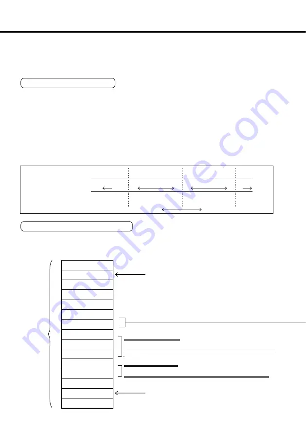
Absolute Data
The absolute data consist of:Single-turn data that defines the absolute position of the motor, and
Multi-turn data that counts the number of turns after the latest clearing operation of the encoder.
1回転データ
CW
CCW
-1 0
0 1
1 2
131071 0,1,2
• • •
• • • 131071 0,1,2
131071 0,1,
多回転データ
モータ回転方向
0Bh
RSW (ID)
D2h
03h
11h
Encoder status (L)
Absolute data
(15 characters)
received
Value of RSW(ID) on the LED touch panel
Encoder status (H)
Single-turn data (L)
Single-turn data (M)
Single-turn data (H)
Multi-turn data (L)
Multi-turn data (H)
00h
Error code
Checksum
After communication is executed,
this value is 0. If not 0, read again
the absolute data from the driver.
Single-turn data
= Single-turn data (H) x Single-turn data (M) x 100h + Single-turn data (L)
Multi-turn data
= Multi-turn data (H) x 100h + Multi-turn data (L)
Structure of Absolute Data
The single- and multi-turn data consist of 15-character data (hexadecimal binary
code) from the RS232C or RS485 communication interface. For the
communication procedure, see pages 23 and 25 in Appendix.
Artisan Technology Group - Quality Instrumentation ... Guaranteed | (888) 88-SOURCE | www.artisantg.com


