


5
Construction and function
5.1 Survey and functional description
The balance is achieved by a presetting with memory position. The calcula-
ted flow rate or pressure loss for each individual pipe can be preset central-
ly and be regulated precisely.
The required values of presetting can be obtained from the flow charts. The
flow charts are valid for the installation of the double regulating and com-
missioning valve in the supply or the return pipe provided the direction of
flow conforms to the arrow on the valve body. All intermediate values are
infinitely adjustable. The selected presetting can be read off two scales
(basic setting longitudinal scale and fine setting peripheral scale, see illus-
tration 7.1).
The limit stop of the presetting is maintained even if the double regulating
and commissioning valve is closed.
The Oventrop double regulating and commissioning valves have two threa-
ded ports which are equipped with the pressure test points for measuring
the differential pressure.
5.2 Markings
• Details of the CE marking on the valve handwheel:
CE marking
• Information on the valve body:
OV
Manufacturer
DN
Nominal size
PN
Nominal pressure
GJL250 / GG25; GJS500-7 / GGG50
Valve body material
6
Installation
Before installing the valve, the pipework has to be flushed thoroughly.
Installation is possible in any position (horizontal, oblique or vertical, in
ascending or descending sections). It is important to note that the direction
of flow must conform to the arrow on the valve body and that the valve
must be installed with L = 3 x Ø of straight pipe in the upstream side and
with L = 2 x Ø in the downstream pipe. The double regulating and commis-
sioning valve can be installed in either the supply or the return pipe.
After installation, the handwheel and measuring connection must be easily
accessible.
The warning notes under paragraph 2 (safety notes) must be
observed!
CAUTION
• Do not use any lubricant or oil when installing the valve as these may
destroy the valve seals. If necessary, all dirt particles and lubricant or oil
residues must be removed from the pipework by flushing the latter.
• When choosing the operating fluid, the latest technical development
has to be considered (e.g. VDI 2035).
• A strainer has to be installed in front of the valve.
• Safeguard from external forces (e.g. impacts, or vibrations).
7
Operation
7.1 Deaeration of the system
Before initial operation, the system has to be filled and bled with due consi-
deration of the permissible working pressures.
7.2 Correction factors for water and glycol mixtures
The correction factors of the antifreeze liquid manufacturers have to be
taken into consideration when setting the flow rate.
7.3 Presetting
1 The preset value of the valve is adjusted by turning the handwheel.
a) The display of the basic setting is shown by the longitudinal scale
together with the sliding indicator. Each turn of the handwheel is repre-
sented by a line on the longitudinal scale.
b) The display of the fine setting is shown by the peripheral scale on the
handwheel together with the marking. The subdivisions of the peri-
pheral scale correspond to 1/10th of a turn of the handwheel.
2 The set value of presetting can be limited by turning the adjustment stem
clockwise until it seats. This can be done by using the long end of a
4 mm Allen key.
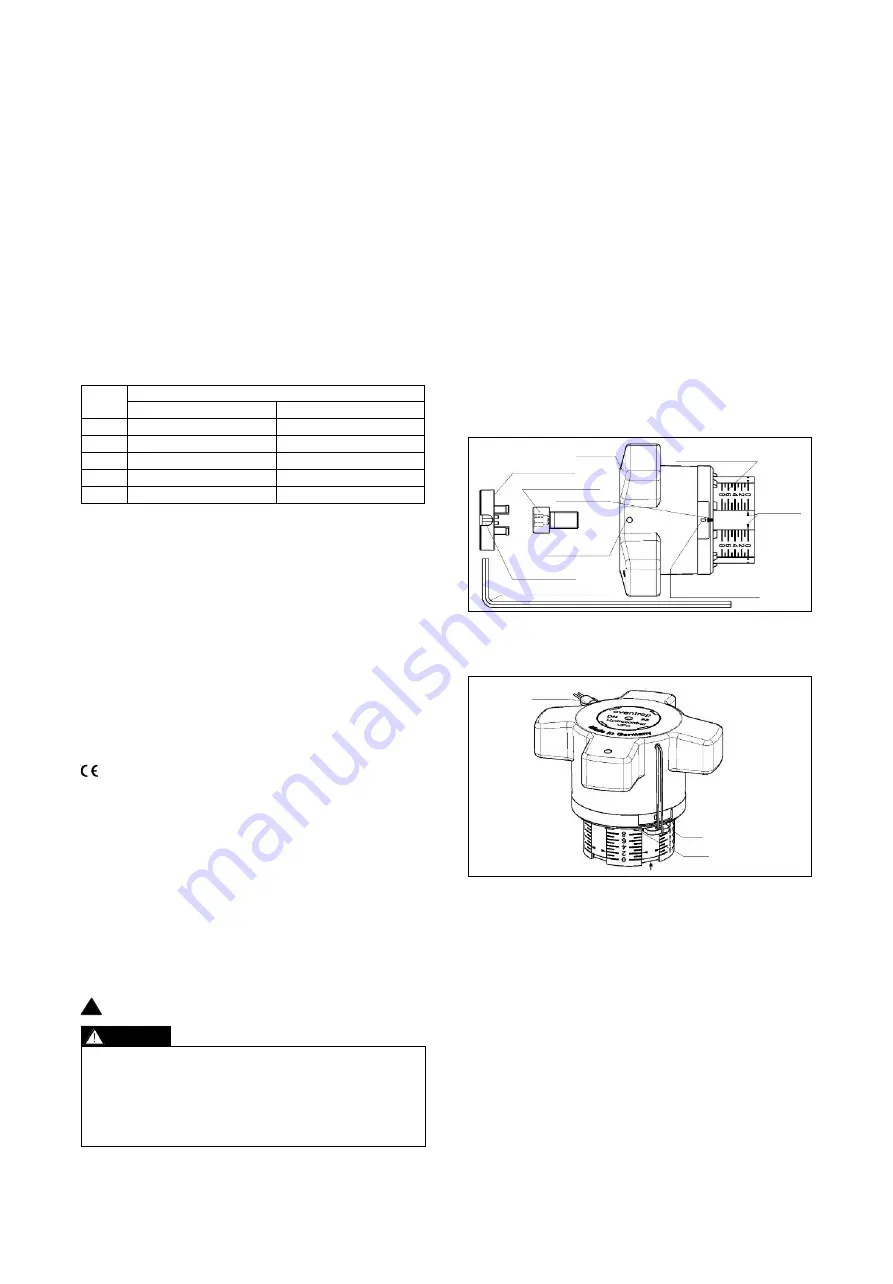
7.4 Visibility/readability of the setting scales
Depending on the installation position of the double regulating and com-
missioning valve, an improvement of the visibility/readability of the setting
scales is obtained by twisting the scales.
With the valve fully closed and the two setting scales on “0”, remove cover
plug, undo screw and with a light tug pull the handwheel from the valve
stem. Next, without altering the presetting (still indicating “0”), adjust the
position of the handwheel so that the display window is clearly visible.
Finally refit the handwheel to the valve stem, tighten the screw and replace
the cover plug.
Illustr. 7.1 Presetting
7.5 Protecting the presetting
The sealing wire may be fitted through the hole in the handwheel and a lead seal may
be fitted.
Illustr. 7.2 Locking the handwheel
7.6 Locking the handwheel
The handwheel can be locked in any position (1/10th of a turn). To do so, push the
enclosed clip into the cut-out of the handwheel below the holes between the guides
until stop (see illustr. 7.2).
The clip can now be sealed as illustrated. It is essential that the sealing wire is fitted
tightly.
8
Accessories
Oventrop offers two measuring gauges for presetting and regulation of the flow rate:
• Oventrop measuring system “OV-DMC 2“
• Oventrop measuring system “OV-DMPC“
The accessories can be found in the catalogue.
9
Maintenance
The valve is maintenance-free.
10 Warranty
Oventrops warranty conditions valid at the time of supply are applicable.
Cover plug
Allen key (4 mm)
Sliding
indicator
Basic setting scale
(longitudinal)
Fine setting scale
(peripheral)
Allen screw
Marking
Hole for
sealing wire
Hole for
sealing wire
Lead seal
Clip
Guide
4.2 Materials
• “Hydrocontrol VFC“
- Round flanges according to DIN EN 1092-2, PN 16
- Round flanges according to DIN EN 1092-2, PN 6
- Hole circle of the flanged connection according to ANSI 150
Valve body made of cast iron (GG 25 / EN-GJL-250 according to DIN EN
1561), bonnet, disc and stem made of bronze / dezincification resistant
brass, disc with PTFE seal. Maintenance-free stem seal due to double
EPDM O-ring.
• “Hydrocontrol VFR“, round flanges according to DIN EN 1092-2, PN 16
Valve body, bonnet and disc made of bronze, stem made of stainless steel,
disc with PTFE seal. Maintenance-free stem seal due to double EPDM
O-ring.
• “Hydrocontrol VFN“, round flanges according to DIN EN 1092-2, PN 25
Valve body made of nodular cast iron (GGG 50 / EN-GJS-500-7 according
to DIN EN 1563), bonnet and disc made of bronze, stem made of dezincifi-
cation resistant brass, disc with PTFE seal. Maintenance-free stem seal due
to double EPDM O-ring.
• “Hydrocontrol VGC“, groove connection for couplings, PN 25
Valve body made of cast iron (GG 25 / EN-GJL-250 according to DIN EN
1561), bonnet, disc and stem made of bronze / dezincification resistant
brass, disc with PTFE seal. Maintenance-free stem seal due to double
EPDM O-ring.
4.3 Weights
DN
65
80
100
125
150
17 / 37
22 / 49
33 / 73
45 / 99
57 / 126
9 / 20
13 / 29
21 / 46
32 / 71
44 / 97
Approx. weight [kg] / [lbs]
Hydrocontrol VFC/VFR/VFN
Hydrocontrol VGC
Once installation is completed, check all installation points for leaks.
!
5
Handwheel


