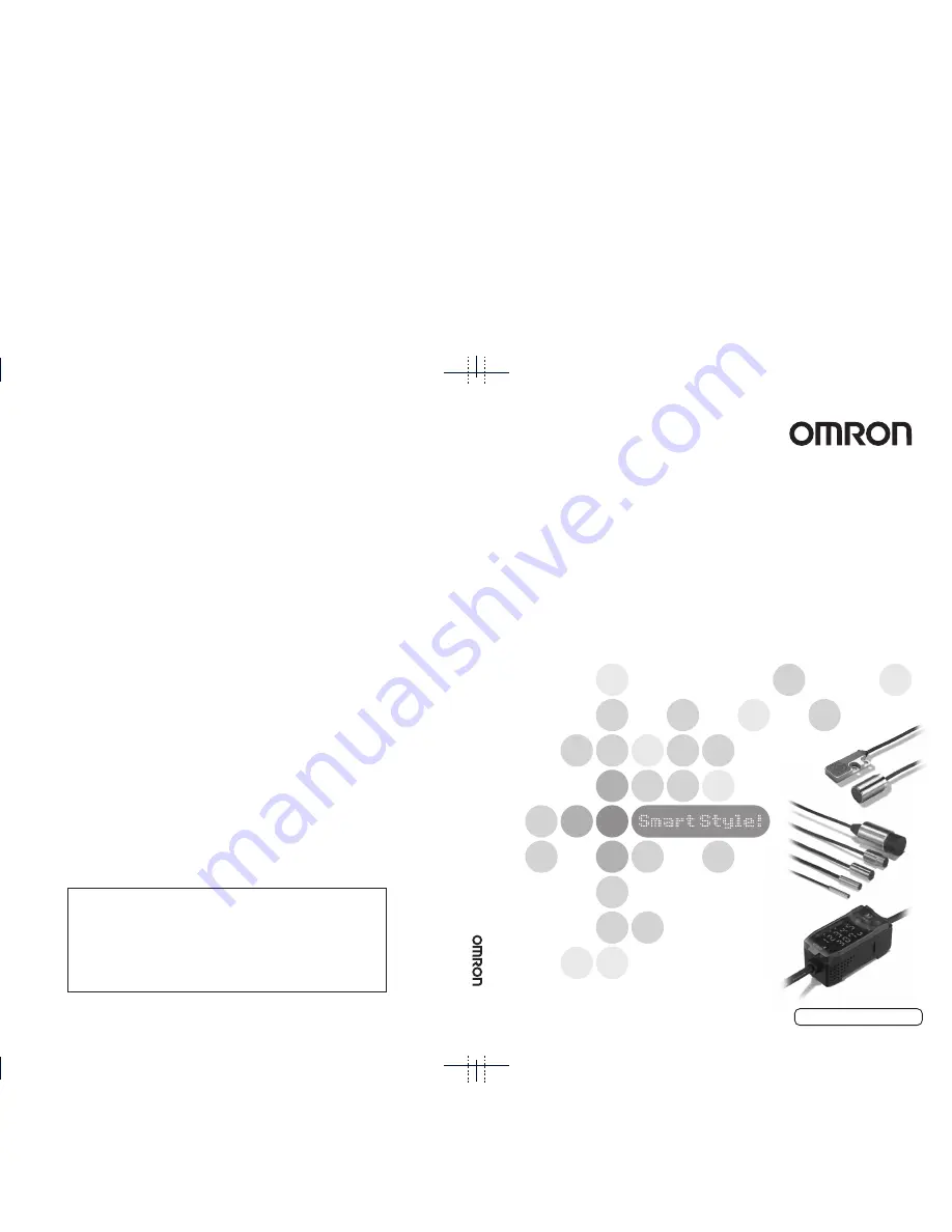
background image

ZX-E Series

Smart Sensors:  Inductive Displacement Type

ZX-E Series Smar

t Sensor

s:

  Inductive Displacement 

T

ype

Operation Manual

Cat. No. Z166-E1-02A

©

OMRON Corporation 2002

        All Rights Reserved.

Note: Specifications subject to change without notice.

Printed in Japan.

0405-0.1M (1002) (M)

Authorized Distributor:

OMRON Corporation

Industrial Automation Company

Sensing Devices Division H.Q.
Application Sensors Division

Shiokoji Horikawa, Shimogyo-ku,
Kyoto, 600-8530 Japan

Tel: (81)75-344-7068/Fax: (81)75-344-7107

Regional Headquarters

OMRON EUROPE B.V.

Sensor Business Unit,
Carl-Benz-Str. 4, D-71154 Nufringen,
Germany
Tel: (49)7032-811-0/Fax: (49)7032-811-199

OMRON ELECTRONICS LLC

1 East Commerce Drive, Schaumburg, IL 60173
U.S.A.

Tel: (1)847-843-7900/Fax: (1)847-843-8568

OMRON ASIA PACIFIC PTE. LTD.

83 Clemenceau Avenue,
#11-01, UE Square,
239920 Singapore

Tel: (65)6835-3011/Fax: (65)6835-2711

OMRON (CHINA) CO., LTD. 

Room 2211, Bank of China Tower,
200 Yin Cheng Road (M)
Shanghai, 200120 China
Tel: (86)21-5037-2222/Fax: (86)21-5037-2200

Operation Man

ual

Cat.

 No.

 Z166-E1-02A

Summary of Contents for ZX-E -

Page 1: ...i Horikawa Shimogyo ku Kyoto 600 8530 Japan Tel 81 75 344 7068 Fax 81 75 344 7107 Regional Headquarters OMRON EUROPE B V Sensor Business Unit Carl Benz Str 4 D 71154 Nufringen Germany Tel 49 7032 811 0 Fax 49 7032 811 199 OMRON ELECTRONICS LLC 1 East Commerce Drive Schaumburg IL 60173 U S A Tel 1 847 843 7900 Fax 1 847 843 8568 OMRON ASIA PACIFIC PTE LTD 83 Clemenceau Avenue 11 01 UE Square 239920...

Page 2: ...y utilize this product and its performance for many years to come This manual describes the functions performance and application methods of a ZX E Smart Sensor To ensure safety read this manual carefully before using the Sensor In addition keep this manual in an easily accessible location for quick reference when needed ...

Page 3: ...ection 5 Section 6 Appendices Index Contents Warranty and Application Considerations Precautions for Safe Use Correct Use and How to Use this Manual Features Preparations for Measurement Basic Operation Main Applications and Setting Methods Detailed Settings Auxiliary Functions Troubleshooting Specifications Characteristic Data etc Operation Manual Smart Sensors ZX E Series ...

Page 4: ...2 Preface ZX E Operation Manual Preface ...

Page 5: ...ty and Application Considerations 7 Precautions for Safe Use 11 Precautions for Correct Use 12 How to Use This Manual 13 Section 1 Features 15 ZX E Features 16 Section 2 Preparations for Measurement 23 Basic Configuration 24 Part Names and Functions 25 Installing the Amplifier Unit 28 Installing Sensor Heads 30 Connections 34 Wiring Output Cables 38 Confirming Warm up Completion 41 ...

Page 6: ...tions and Setting Methods 61 Detecting Bottom Deadpoint 62 Measuring Height 67 Measuring Eccentricity and Vibration 71 Measuring Thickness 74 Section 5 Detailed Settings 79 Setting Number of Samples to Average 80 Using Hold Functions 81 Comparing Measured Values Previous Value Comparisons 88 Changing Display Scales 90 Entering Threshold Values 97 Linear Output 103 Setting Judgement Output Timing T...

Page 7: ...Units 116 Changing the Number of Display Digits 123 Reversing the Display 124 Adjusting Display Brightness ECO Display 126 Using the Zero Reset Function 127 Key Lock Function 132 Initializing Settings Data 133 Appendices 135 Troubleshooting 136 Error Messages and Countermeasures 137 Q A 138 Glossary 139 Specifications and Dimensions 140 Characteristic Data 148 Quick Reference for Displays 157 Inde...

Page 8: ...6 Preface Contents ZX E Operation Manual Preface ...

Page 9: ...ING THE PRODUCTS UNLESS OMRON S ANALYSIS CONFIRMS THAT THE PRODUCTS WERE PROPERLY HANDLED STORED INSTALLED AND MAINTAINED AND NOT SUBJECT TO CONTAMINATION ABUSE MISUSE OR INAPPROPRIATE MODIFICATION OR REPAIR SUITABILITY FOR USE THE PRODUCTS CONTAINED IN THIS DOCUMENT ARE NOT SAFETY RATED THEY ARE NOT DESIGNED OR RATED FOR ENSURING SAFETY OF PERSONS AND SHOULD NOT BE RELIED UPON AS A SAFETY COMPONE...

Page 10: ...ents and other reasons It is our practice to change model numbers when published ratings or features are changed or when significant construction changes are made However some specifications of the product may be changed without any notice When in doubt special model numbers may be assigned to fix or establish key specifications for your application on your request Please consult with your OMRON r...

Page 11: ...9 ZX E Operation Manual Preface PREFACE ...

Page 12: ...10 Preface ZX E Operation Manual PREFACE ...

Page 13: ...or the Smart Sensor together with high voltage lines or power lines Doing so or placing them into the same duct can cause induc tion and lead to malfunction or damage Always turn OFF the power supply before wiring and before connecting or disconnect ing connectors Settings When setting the threshold value with the Smart Sensor connected to an external device turn ON the Amplifier Unit s judgement ...

Page 14: ...vapor Installation and Handling of Components Power Supply and Wiring Do not extend the Sensor Head cable by more than 8 m Use a ZX XC A Extension Cable order separately to extend the cable from the Sensor Use a shielded cable to extend the Amplifier cable The shielded cable must have the same specifications as that of the Amplifier cable When using a commercially available switching regulator gro...

Page 15: ...provided This page does not actually exist in this manual Section 3 Basic Operations ZX E Smart Sensor linearity is adjusted before shipment however more accurate linearity can be obtained by adjusting linearity again for the actual sensing objects and operating environment Adjusting Linearity This section describes how to set the sensing object material Selecting Sensing Object Material To use th...

Page 16: ...in ALL CAPS Procedures The order for the procedures is indicated by numbered steps Visual Aids Provides information on important operating procedures gives advice on how to use functions and highlights important performance information Indicates pages with relevant information Indicates useful information for when problems arise ...

Page 17: ...Section 1 FEATURES 15 ZX E Operation Manual Section 1 FEATURES ZX E Features 16 ...

Page 18: ...on 1 FEATURES ZX E Features The ZX E Smart Sensor measures the distance between the Sensor Head and the sensing object Example Detecting the Bottom Deadpoint on a Press Machine Measurement detail Sensing object Distance Measurement output Judgement outputs ...

Page 19: ...ed after warming up has been completed See page 41 Many Simple Functions Measurement Ready at Power ON The Smart Sensor can be used simply by installing and wiring it Simply turn ON the power and it s ready to operate The measurement distance is displayed on the Amplifier Unit Warming up in progress Warming up completed Time lapsed after power up min Fluctuation of measured value Below specified r...

Page 20: ...e cute precise linearity adjustment Time consuming offset and range adjustments are not required Precise adjustment is also possible for non ferrous sensing objects p 54 Simple Calculation Settings Use a Calculating Unit to simply measure thickness and sum and difference calcula tions between two measurements p 116 Rated measurement distance 0 50 100 Thickness Calculating Unit ...

Page 21: ...ention function which allows multiple Sensor Heads to be mounted close to each other This function is supported for up to five Sensor Heads by using ZX CAL2 Calculating Units p 26 and p 120 Compatibility between Sensor Heads and Amplifier Units Amplifier Units do not need to be changed when Sensor Heads are changed for main tenance or to switch to new products Calculating Units ...

Page 22: ...Operation Manual Section 1 FEATURES Extendable Sensor Head Cables An extension cable with a maximum length of 8 m can be connected The ZX XC A Extension Cable is required to extend the Sensor Head cable p 24 Extension Cable Up to 8 m ...

Page 23: ...r gins while viewing the resolution value p 51 Confirm Measurement Status on a Personal Computer Use an Interface Unit and Smart Monitor V2 to view measurement waveforms and log measurement data on a personal computer This function is useful for making on site measurement adjustments and for day to day quality control p 24 Resolution Resolution Deviation to be detected Smart Monitor V2 Interface U...

Page 24: ...22 Section 1 ZX E Features ZX E Operation Manual Section 1 FEATURES ...

Page 25: ...R MEASUREMENT 23 ZX E Operation Manual Section 2 PREPARATIONS FOR MEASUREMENT Basic Configuration 24 Part Names and Functions 25 Installing the Amplifier Unit 28 Installing Sensor Heads 30 Connections 34 Wiring Output Cables 38 ...

Page 26: ...mplifier Units from a personal computer and monitors measured values Personal computer Interface Unit ZX SF11 Version 2 0 or later Used when connecting a personal computer Basic Configuration Sensor Heads ZX ED T ZX EM T ZX EV T Sensor Heads detect the sensing objects Extension Cables ZX XC1A 1 m ZX XC4A 4 m ZX XC8A 8 m Used between Sensor Heads and Amplifier Units Amplifier Units ZX EDA11 or ZX E...

Page 27: ...ment result is HIGH 9 The PASS indicator lights when the judgement result is PASS 10 The LOW indicator lights when the judgement result is LOW 11 The main display shows measured values and function names 12 The sub display shows additional information and function settings for measurements Reading Displays p 47 13 The threshold switch selects whether to set and display the HIGH or LOW threshold 14...

Page 28: ...ONS FOR MEASUREMENT Sensor Heads Calculating Units Sensor head Preamplifier Connector Connects to Amplifier Unit Display Connectors one on each side two total Connects to Amplifier Unit Connector indicators Light when Calculating Unit is connected to Amplifier Units Display Detail ...

Page 29: ...n the power is turned ON 4 BUSY Lights during communications with the Smart Sensor ERR Lights if an error occurs during communications with the Smart Sensor 5 BUSY Lights during communications with the personal computer ERR Lights if an error occurs during communications with the computer Display 1 Communications Connector 2 Amplifier Unit Connector 3 Power supply indicator 4 Sensor communications...

Page 30: ...k the connector end of the Amplifier Unit on the DIN Track and press in at the bot tom until the Unit locks into place Always hook the connector end of the Amplifier Unit on the DIN Track first Mounting strength may decrease if the output cable end is hooked on the DIN Track first DIN Track order separately PFP 100N 1 m PFP 50N 0 5 m PFP 100N2 1 m End Plates order separately PFP M Hook on the conn...

Page 31: ...29 ZX E Operation Manual Section 2 Installing the Amplifier Unit Section 2 PREPARATIONS FOR MEASUREMENT Removal Method Push the Amplifier Unit up and pull out from the connector end ...

Page 32: ...lowing table When using the ZX EM02HT consider the thermal expansion caused by the rise in temperature of the sensing object and make sure that the sensing object does not touch the sensing surface Even when operated within the specified temperature range using in locations subject to extreme temperature fluctuations may result in deterioration of Sensor characteristics When using the ZX EM02HT ma...

Page 33: ... smaller than standard sensing object or a non ferrous object is used the predetermined characteristics may not be obtained Characteristic Data p 148 Influence of Surrounding Metal Separate the Sensor Head from surrounding metals by at least the distances shown in the following diagram Sensing object Ferrous object 18 18 mm or larger 0 5 mm Example ZX ED01T Sensor Head Measurement distance 0 to 1 ...

Page 34: ...owing diagram The distance between Sensor Heads can be further reduced when the Sensor Heads are side by side if the mutual interference prevention function is used Performing Calculations p 116 Unit mm Model A B Mutual Interference Prevention Function Used Not used ZX EDR5T 5 3 1 20 ZX ED01T 10 5 4 50 ZX ED02T 20 8 50 ZX EM02T 20 10 50 ZX EM07MT 100 30 150 ZX EV04T 80 14 50 ZX EM02HT 20 12 50 Fac...

Page 35: ...5 mm DIN Track Use the ZX XBE2 Preamplifier DIN Track Mounting Bracket order separately when mounting the Preamplifier to DIN Track 1 Use M3 screws to fix the enclosed Preampli fier mounting bracket 2 Snap one end of the Preamplifier into the bracket 3 Then snap the other end of the Preamplifier into the bracket Removal Method Hold the center of the Preamplifier and lift Mounting Dimensions Unit m...

Page 36: ...hile the power is ON Sensor Heads Do not touch the terminals inside the connector Connection Method Push the Sensor Head connector into the Amplifier Unit connector until it locks Removal Method When disconnecting the Sensor Head hold the connector ring and the Amplifier Unit connector and pull them straight out Do not pull only on the connector ring because the input cable of the Amplifier Unit m...

Page 37: ...ed Provide power to all connected Amplifier Units Connection Method 1 Open the connector covers on the Amplifier Units Open the connector covers by lifting and sliding them open 2 Mount the Calculating Unit to the DIN Track 3 Slide and connect the Calculating Unit to the Amplifier Unit connector 4 Slide and connect the second Amplifier Unit to the Calculating Unit connector Perform the above opera...

Page 38: ...ction 2 Connections ZX E Operation Manual Section 2 PREPARATIONS FOR MEASUREMENT Channel Numbers of Amplifier Units The following diagram shows the channel numbers when multiple Amplifier Units are connected ...

Page 39: ... the connector cover on the Amplifier Unit Open the connector cover by lifting and sliding it open 2 Mount the Interface Unit to the DIN Track 3 Slide and connect the Interface Unit to the Amplifier Unit connector Perform the above operation in the reverse order to remove Interface Units When multiple Amplifier Units are used connect the Interface Unit to the Amplifier Unit with the highest channe...

Page 40: ...s 6 The linear output outputs a current or voltage output in accordance with the measured value 7 The linear output GND terminal is the 0 V terminal for the linear output Use a different ground for the linear output from the normal ground Always ground the linear output terminal even when linear output is not used 8 When the judgement output hold input is turned ON the judgement outputs are held a...

Page 41: ...output 10 kΩ min Load Current output 4 to 20 mA Current voltage output selector Internal circuit Brown 12 to 24 V DC White HIGH judgement output Green PASS judgement output Gray LOW judgement output 12 to 24 V DC Blue GND 0 V Pink Judgement output hold input Purple Timing input Orange Zero reset input Red Reset input Black Linear output Shield Linear ground Voltage output 4 V 100 Ω ...

Page 42: ...rent output 4 to 20 mA Current voltage output selector Internal circuit Brown 12 to 24 V DC White HIGH judgement output Green PASS judgement output Gray LOW judgement output 12 to 24 V DC Blue GND 0 V Pink Judgement output hold input Purple Timing input Orange Zero reset input Red Reset input Black Linear output Shield Linear ground Voltage output 4 V 100 Ω Load Load Load ...

Page 43: ...ll flash W UP to show that the Sensor is warming up Warm up requires approximately 5 to 15 minutes When warming up has been completed the normal display will be shown Measurement operations can be performed while in warm up display status but the precision of measurements before warming up has been completed will be low For high precision measure ments wait until warming up has been completed SUB ...

Page 44: ...42 Section 2 Confirming Warm up Completion ZX E Operation Manual Section 2 PREPARATIONS FOR MEASUREMENT ...

Page 45: ...nowledge for Operation 46 Switching Modes 46 Reading Displays 47 Key Operations 48 Setting Conditions 49 Inputting Numerals 50 Function Transition Charts 51 Adjusting Linearity 54 Selecting Sensing Object Material 54 Entering Adjustment Values 56 Executing Adjustment 58 Initializing Adjustment Settings 59 ...

Page 46: ...or the Application Detecting Bottom Deadpoint Measuring Height Measuring Thickness Measuring Eccentricity and Vibration Setting and Changing Measurement Data Setting Number of Samples to Average Using Hold Functions Comparing Measured Values Previous Value Comparison Changing Display Scales Setting Judgement Conditions Entering Threshold Values Setting Output Data Linear Output Setting Judgement O...

Page 47: ...or Digital Displays Applied Settings Measuring with Multiple Amplifier Units Performing Calculations Preventing Mutual Interference between Saving Zero Reset Level Setting Offset Values for Zero Reset Additional Functions Changing the Number of Display Digits Using ECO Display Function Reversing the Display Key Lock Function Initializing Settings Data Changing Setttings p 136 p 139 p 120 p 116 p 1...

Page 48: ...n Switching Modes The ZX E has three modes Use the Mode Switch on the Amplifier Unit to switch between modes Switch to the desired mode before starting operation Function Transition Charts p 51 Mode Description RUN Normal operation mode T Mode for setting the threshold values FUN Mode for setting measurement conditions ...

Page 49: ...ue actual mea sured value threshold value output value and resolution in order when the Control Keys are pressed Threshold Value Display Displays either the HIGH or LOW threshold value depending on the position of the threshold switch The monitor focus setting determines whether the value is output as voltage or current Output Settings Monitor Focus p 103 T Displays the measured value the value af...

Page 50: ...de Cursor Keys LEFT Key RIGHT Key Changes sub display content Used when selecting numeral digits Function changes depend ing on setting Switches function display Selects numeral digit Stops setting UP Key Performs timing input Used when changing numerals Function changes depend ing on setting Switches between selections Changes numerals DOWN Key Resets input ENT Key Performs zero reset Function ch...

Page 51: ...urement conditions Changing to FUN Mode and HOLD 1 Set the mode switch to FUN 2 Use the LEFT and RIGHT Keys to display HOLD on the main display Setting Hold Conditions 3 Press either the UP or DOWN Key The present set value will flash on the sub display 4 Use the UP and DOWN Keys to select P H Press either the LEFT or RIGHT Key to cancel the selected option The display will return to the current s...

Page 52: ... first digit on the sub display will flash and direct input will be enabled 4 Use the LEFT or RIGHT Key to move the cur sor to the first decimal place 5 Use the UP or Down Key to display 1 6 Repeat steps 4 and 5 to move the cursor to the second decimal place and display 9 To cancel the selected setting use the LEFT Key to move the cursor to the leftmost digit and press the LEFT Key again Alternati...

Page 53: ...p 139 T Mode There is no function transition in T mode The numerals shown in the above diagram are an example only The actual display may be different In RUN and T modes the position of the threshold switch will determine whether the HIGH or LOW threshold will be displayed Main display Sub display Measured value See note The main display always shows the measured value Present value See note Note ...

Page 54: ...Clamp value setting Settings for non measurement Mutual interfer ence prevention See note 3 Note 1 Linearity adjustment is dis played first when you enter FUN mode When CLOSE is selected the special functions will not be displayed and the display will return to LINER Note 2 Previous value compari son is displayed when hold is not set to OFF Note 3 Mutual interference prevention is displayed only o...

Page 55: ... This symbol indicates that after the ENT Key has been pressed to confirm the selection the LEFT and RIGHT Keys should be pressed to move through the menu Delay hold Delay time Timer Special 2 sensor operation Sampling period Self trigger level Self trigger hys teresis width Settings initialization Thickness setting mode Timer time setting See note 4 p 86 p 86 p 86 p 112 p 83 p 83 p 116 p 116 p 13...

Page 56: ...ions Linearity should also be adjusted again when Sensor Heads are replaced Flow of Operation Linearity p 139 Selecting Sensing Object Material This section describes how to set the sensing object material Linearity According to Material Characteristic Data p 148 To use the default linearity adjustment after changing materials select the material and then perform Executing Adjustment Selecting Sen...

Page 57: ...itch to FUN 2 Use the LEFT or RIGHT Key to display LINER on the main display Setting Sensor Object Material 3 Press the ENT Key METAL will be displayed 4 Press the UP or DOWN Key The sub display will flash 5 Use the UP or DOWN Key to select the mate rial 6 Press the ENT Key to confirm the selection The setting will be registered ...

Page 58: ...h 0 then 50 and 100 of the measure ment distance To simply replace the sensing object material and use the default linearity adjustment skip this oper ation and perform Executing Adjustment Entering Adjustment Value for 0 Position 1 Set the sensing object at the 0 position 2 Use the LEFT and RIGHT Keys to display D000 3 Press the ENT Key The sub display will show OK and the adjustment value will b...

Page 59: ...show OK and the adjustment value will be registered Press the ENT Key again to reinput the adjust ment value Entering Adjustment Value for 100 Position 7 Move the sensing object to the 100 posi tion 8 Use the LEFT or RIGHT Keys to display D100 9 Press the ENT Key The sub display will show OK and the adjustment value will be registered Press the ENT Key again to reinput the adjust ment value Rated ...

Page 60: ... When the adjustment data has been registered the sub display will show OK If the sub display shows ERRTB there has been a mis take in the settings Check the material selected for the sensing object and the set positions and register the set tings again Cancelling Adjustment The adjustment settings will be cleared if the adjustment is cancelled 1 Use the LEFT and RIGHT Keys to display TABLE on the...

Page 61: ...ettings use the INIT function Initializing Settings Data p 133 Moving to FUN Mode and LINER 1 Set the mode switch to FUN 2 Use the LEFT and RIGHT Keys to display LINER on the main display Initializing Settings 3 Press the ENT Key The display will show METAL 4 Use the LEFT and RIGHT Keys to display LINIT 5 Press and hold down the ENT Key One dash at a time will appear on the sub display 6 Release t...

Page 62: ...60 Section 3 Adjusting Linearity ZX E Operation Manual Section 3 BASIC OPERATION ...

Page 63: ...PPLICATIONS AND SETTING METHODS 61 ZX E Operation Manual Section 4 MAIN APPLICATIONS AND SETTING METHODS Detecting Bottom Deadpoint 62 Measuring Height 67 Measuring Eccentricity and Vibration 71 Measuring Thickness 74 ...

Page 64: ...e When making settings while still connected to an external device set the Amplifier Unit s judgement output hold input to ON so that the output to the external device remains unchanged Adjust linearity before executing this operation Adjusting Linearity p 54 Flow of Operation Mounting Sensor to Press Adjusting Detection Position Setting Bottom Deadpoint Position Setting Measurement Timing Setting...

Page 65: ...s p 30 Use a ferrous sensing object and one that is as large as or larger than the standard sensing object Sensing object p 143 Adjusting Detection Position Adjust the position of the Sensor Head so that when the press machine is set at the bottom deadpoint position the distance between the Sensor Head and the sensing object is about half of the measurement distance Refer to the Amplifier Unit dis...

Page 66: ...mode and lower the stripper or top mold to the bottom deadpoint 2 Adjust the position of the Sensor Head so that this position is at about half of the measure ment distance The measured value will be displayed on the Amplifier Unit Refer to this display while adjusting the Sensor Head Stripper or top mold Bottom mold 1 2 the measurement distance ...

Page 67: ...nt To ignore bounding when measuring during press operation specify a time delay from the timing signal to when sampling starts When the timing signal cannot be input from the device set a self down trigger Refer to Section 5 Detailed Settings for details on settings Using Hold Functions p 81 Measured value Self trigger level The bottom value is held Timing input Delay time Sampling period ...

Page 68: ...set Values p 128 Setting Tolerance Judgement Values Set the upper and lower limits the HIGH and LOW threshold values for the PASS OK range for the reference value set in step The HIGH PASS and LOW judgement results will be output based on the threshold values set here Refer to Section 5 Detailed Settings for details on operation Entering Threshold Values p 97 Bottom deadpoint Setting Description H...

Page 69: ... device set the Amplifier Unit s judgement output hold input to ON so that the output to the external device remains unchanged Adjust linearity before performing measurement Adjusting Linearity p 54 Flow of Operation Place an actual sensing object in position Have a reference sample ready beforehand Rivet Metal Plate Resin Mounting to Device Adjusting Measurement Distances Measuring Reference Samp...

Page 70: ...position and adjust the Sensor Head position Refer to the Amplifier Unit display and adjust the Sensor Head position so that the upper and lower limits of the height H to be measured fall within the measurement distance Measurement distance p 143 Measured Value Display The Amplifier Unit display shows the distance H from the reference sample default The display can also be set to show the height o...

Page 71: ...g period is held When the timing signal cannot be input from the device set a self down trigger The following settings are required when the reference sample height is displayed using the scaling function Measurement trigger Self up trigger Hold condition Peak hold Refer to Section 5 Detailed Settings for details on settings Using Hold Functions p 81 Measured value Sampling Self trigger level The ...

Page 72: ... Teaching p 99 The reference sample height can also be set to 0 Using the Zero Reset Function p 127 Setting Tolerance Judgement Values Refer to the HIGH threshold registered in step and set the upper and lower limits HIGH and LOW thresholds for a PASS OK judgement The HIGH PASS and LOW judgement results will be output based on the threshold values set here Refer to Section 5 Detailed Settings for ...

Page 73: ...centricity of a shaft When making settings while still connected to an external device set the Amplifier Unit s judgement output hold input to ON so that the output to the external device remains unchanged Adjust linearity before performing this operation Adjusting Linearity p 54 Flow of Operation Metal shaft Mounting to Device Adjusting Measurement Distances Setting Tolerance Judgment Values Meas...

Page 74: ... diagram and prepare a mounting jig Installing Sensor Heads p 30 Adjusting Measurement Distances Adjust the position of the Sensor Head so that the distance H between the Sensor Head and the sensing object is about half the measurement distance as shown in the diagram Refer to the Amplifier Unit display while adjusting the Sensor Head position Measurement distance p 143 Mounting jig resin or metal...

Page 75: ...old Functions p 81 Setting Tolerance Judgment Values Refer to the deflection measured in step and set either the upper limit HIGH threshold or lower limit LOW threshold for a PASS OK judgement The judgement result will be output based on the threshold value set here The output will depend on the type of threshold set Output when upper limit is set PASS or HIGH Output when lower limit is set PASS o...

Page 76: ...making settings while still connected to an external device set the Amplifier Unit s judgement output hold input to ON so that the output to the external device remains unchanged Adjust linearity before performing this operation Adjusting Linearity p 54 Flow of Operation Steel plate Mounting to Device Adjusting Setting Distances Setting Expressions Preventing Mutual Interference Setting Tolerance ...

Page 77: ...s displayed on i e output to the CH2 Amplifier Unit Connect the CH2 output cable to the external device to enable external control Connections p 34 The CH1 Amplifier Unit will display output the measurement result for the CH1 Sensor Head only Mounting Sensor Heads to Inspection Device Refer to the following diagram and prepare mounting jigs Mount the Sensor Heads fac ing each other Installing Sens...

Page 78: ...e Sensor Heads Measurement distance p 143 Preventing Mutual Interference Mutual interference prevention settings are required when the distance between Sen sor Heads is less than the mutual interference distance These settings are not required if the Sensor Heads are further apart than the mutual interference distance For information on mutual interference distance refer to Mutual Interference p 3...

Page 79: ...gistered The thickness is measured based on the positional rela tionship of the Sensor Heads Refer to Section 6 Auxiliary Functions for details on settings Performing Calculations p 116 Setting Tolerance Judgement Values Set the upper and lower limits HIGH and LOW thresholds for the thickness for a PASS OK judgement The HIGH PASS and LOW judgement results will be output based on the threshold valu...

Page 80: ...78 Section 4 Measuring Thickness ZX E Operation Manual Section 4 MAIN APPLICATIONS AND SETTING METHODS ...

Page 81: ...ion 5 DETAILED SETTINGS Setting Number of Samples to Average 80 Using Hold Functions 81 Comparing Measured Values Previous Value Comparisons 88 Changing Display Scales 90 Entering Threshold Values 97 Linear Output 103 Setting Judgement Output Timing Timer 112 ...

Page 82: ...sponse time of the judgement outputs and linear output will be increased Moving to FUN mode and AVE 1 Set the mode switch to FUN 2 Use the LEFT and RIGHT Keys to display AVE on the main display Selecting Number of Samples to Average 3 Press the UP or DOWN Key The sub display will flash 4 Use the UP and DOWN Keys to select the number of samples to average 5 Press the ENT Key to confirm the selectio...

Page 83: ...MP value p 110 Any of the 5 settings shown in the table can be selected as the value to hold 3 2 1 Selecting Hold Condition for Measured Values Setting the Trigger for Measurement in Hold Mode Setting Delay Time If required Selection Details OFF Default Hold measurement is not performed The measured value is always output P H Peak hold Holds the maximum value during the sampling period The output ...

Page 84: ...n detecting vibration The output changes at the end of the sampling period and is held until the end of the next sampling period S H Sample hold Holds the measured value at the start of the sampling period The output changes at the start of the sampling period and is held until the start of the next sampling period AVE H Average hold Holds the average measured value during the sampling period The ...

Page 85: ... up trigger The sampling period is the period that the measured value is greater than the specified self trigger level Hold measurement is possible without a sync input When a delay time is set the timing when the measured value becomes smaller than the self trigger level and the end of the sampling period will not be synchronous Sampling will end after the specified sampling period has expired DO...

Page 86: ... Press the ENT Key to confirm the selection The selected trigger type will be registered Setting Trigger Levels when UP or DOWN Is Selected 5 Use the RIGHT or LEFT Key to display H LVL on the main display H LVL will not be displayed if timing input TIMIG is selected as the trigger 6 Press the UP or DOWN Key The leftmost digit of the sub display will flash 7 Use the Cursor Keys to set the trigger l...

Page 87: ...n the main display H HYS will not be displayed if timing input TIMIG is set as the trigger 10 Press the UP or DOWN Key The leftmost digit of the sub display will flash 11 Use the Cursor Keys to set the hysteresis width for the trigger level 12 Press the ENT Key to confirm the setting The hysteresis width will be registered Move between digits Increment and decre ment the numeric value ...

Page 88: ...and sampling period less than the timing input ON interval If the next timing input for measurement is received before the delay and sampling period have passed that timing input will be ignored and will not be reflected in the sampling Moving to Delay Hold H DLY 1 Use the LEFT and RIGHT Keys to display H DLY on the main display H DLY will not be displayed if the delay conditions are set to OFF 2 ...

Page 89: ...ey to confirm the setting The delay time will be registered Setting Sampling Period 9 Use the LEFT and RIGHT Keys to display H S T on the main display H S T will not be displayed if the H DLY function is set to OFF 10 Press the UP or DOWN Key The leftmost digit of the sub display will flash 11 Use the Cursor Keys to enter the sampling period ms 12 Press the ENT Key to confirm the setting The sampl...

Page 90: ...arison can be set The difference from the previous hold value with a PASS judgement becomes the measured value For example if the judgement for that previous measurement is HIGH or LOW the comparison is performed with the hold value before that The hysteresis width setting will be disabled if the previous value comparison function is used Hysteresis Setting p 102 Moving to FUN mode and SPCL 1 Set ...

Page 91: ...y will flash 4 Use the UP and DOWN Keys to display SET or ALL 5 Press the ENT Key 6 Use the LEFT and RIGHT Keys to display COMP on the main display Setting Previous Value Comparison 7 Press the UP or DOWN Key The sub display will flash 8 Use the UP and DOWN Keys to display ON 9 Press the ENT Key to confirm the setting The previous value comparison function can now be used ...

Page 92: ...after scaling is executed the display will be 19 999 If the measurement result is greater than the maximum the display value will be 59 999 Scaling Application Example Purpose Settings Method To display distance from Sensor Head Offset the display value One pointscaling with no inverted display values p 92 To display the height of the sensing object Offset the display value and invert the relation...

Page 93: ...vel p 83 Output Settings Monitor Focus p 103 Using the Zero Reset Function p 127 Finding Thicknesses p 118 To correct display values to match actual dis tances Offset the display value and change the dis play value range Two point scaling p 95 Purpose Settings Method Sensor Head Actual distance 1 0 mm Value to display 0 8 mm Sensing object Actual distance 0 2 mm Value to display 0 3 mm Sensing obj...

Page 94: ...e set This section describes how to make settings for one point scaling using an different example Example Displaying the Height of the Sensing Object Moving to FUN mode and SPCL 1 Set the mode switch to FUN 2 Use the LEFT and RIGHT Keys to display SPCL on the main display Moving to SCALE 3 Press the UP or DOWN Key The sub display will flash 4 Use the UP and DOWN Keys to display SET or ALL 5 Press...

Page 95: ...e ENABLE indicator will be lit when the sensing object is within the measurement distance Scaling is not possible if the sensing object is not within the distance 11 Press one of the Cursor Keys The current measured value will be displayed on the main display The leftmost digit of the sub display will flash 12 Use the Cursor Keys to set the offset for the measured value on the sub display The posi...

Page 96: ...17 Press the ENT Key to confirm settings The sub display will be P2SCL 18 Press the ENT Key Confirming that Scaling Is Completed If scaling has been completed correctly the display will be OK If scaling was unable to be completed the display will be NG Check that the sensing object is within the measurement distance and execute scaling again Options Details D FWD Not inverted D INV Inverted Invert...

Page 97: ...fied points by at least 1 of the rated measurement distance for the con nected Sensor For example the rated measurement distance for the ZX ED01T Sensor is 1 mm Therefore the two specified points must be separated by 10 µm min Setting the First Point 1 Set the first point by following steps 1 to 15 of the one point scaling procedure p 92 The range for two point scaling is automatically set based o...

Page 98: ...h 4 Use the Cursor Keys to set the offset for the measured value The position of the decimal point can be changed using the next steps 5 Press the ENT Key to confirm the settings The decimal point will flash 6 Use the LEFT and RIGHT Keys to move the decimal point 7 Press the ENT Key to confirm this setting Confirming the Completion of the Scaling Settings If scaling has been completed correctly th...

Page 99: ...e HIGH PASS and LOW Method Details Direct input Sets threshold values by direct numerical value input Direct input is useful when you know the dimensions for an OK judgement or when you want to fine tune threshold values after teaching Position teaching Performs measurement and uses the measurement results to set threshold values Position teaching is useful when threshold samples i e with the uppe...

Page 100: ...the threshold being set value for the threshold switch selection will be displayed on the sub display 3 Press one of the Cursor Keys The leftmost digit of the threshold value will flash on the sub display 4 Use the Cursor Keys to set the threshold value 5 Press the ENT Key to confirm the settings The threshold values will be registered Countermeasures for Setting Errors One of the following two er...

Page 101: ...current measured value is shown on the main dis play and the threshold being set the value for the thresh old switch selection will be displayed on the sub display 3 Place the threshold sample in position The main display value changes 4 Press the ENT Key for at least one second and then release The measured value at the point that the ENT Key is released will be set as the threshold value This th...

Page 102: ...useful when you want to set threshold values by starting the device and obtaining real measurements Hold trigger mode and scaling settings that have been made before teaching are reflected in the teaching measurements Moving to T Mode 1 Set the mode switch to T 2 Start the device The threshold switch can be set to either position Both HIGH and LOW thresholds will be set regardless of the switch se...

Page 103: ...he ENT and RIGHT Keys to end measurement The maximum measured value during the measurement period will be set as the HIGH threshold value and the minimum will be set as the LOW threshold value The new threshold value either HIGH or LOW depend ing on the threshold switch setting will be displayed on the sub display If ERRLH is displayed p 98 The threshold values set using automatic teaching can be ...

Page 104: ... to FUN 2 The main display will show HYS 3 Press the UP or DOWN Key The leftmost of the sub display will flash 4 Use the Cursor Keys to enter the hysteresis width 5 Press the ENT Key to confirm the setting The hysteresis width will be registered Countermeasures for Setting Errors If ERROV is displayed HIGH threshold value LOW threshold value hysteresis width If an error is displayed the threshold ...

Page 105: ...lues for any two current values or voltage values to set the output range Example Setting 0 2 mm to 4 mA Output and 0 8 mm to 20 mA Output for Current Output Separate the two specified points by at least 1 of the rated measurement distance for the con nected Sensor For example the rated measurement distance for the ZX ED01T Sensor is 1 mm Therefore the two specified points must be separated by 10 ...

Page 106: ...er supply to the Amplifier Unit 2 Move the current voltage switch to current out put The switch is found on the bottom of the Amplifier Unit Moving to FUN Mode and SPCL 3 Turn ON the power supply and move the mode switch to FUN 4 Use the LEFT and RIGHT Keys to display SPCL on the main display Moving to FOCUS 5 Press the UP or DOWN Key The sub display will flash 6 Use the Up and DOWN Keys to displa...

Page 107: ...urrent value will be displayed on the main display and the corresponding measured value will be displayed on the sub display and the leftmost digit will flash 12 Set the output current value and the corre sponding measured value for the first point Set a measured value within the measurement distance If scaling or calculation has been set set a value that reflects those settings The flashing digit...

Page 108: ...d point 15 Press the ENT Key to confirm the settings Confirming Completion of Monitor Focus Settings The display will read OK if monitor focus has been set correctly The display will be NG if the settings are incorrect If the settings are incorrect check the following points and execute the monitor focus again Is the measured value set on the sub display within the measurement distance with scalin...

Page 109: ... are corrected by entering the correction value for the current or volt age values for any two points Set the monitor focus function and select either current or voltage output beforehand p 103 This section uses a current output as an example Change the values in this example for voltage output as necessary 1 Connect the linear output to an external ammeter Moving to FUN Mode and SPCL 2 Turn ON th...

Page 110: ...the sub display so that the ammeter reading and the output current shown on the main display are the same The larger the correction value the larger the output current The correction value can be set within the range 999 to 999 To set a negative value make the leftmost digit of the sub display flash and change the value The flashing digit i e the digit for which a value can be set will change as s...

Page 111: ...t to set the correction value for the second point 12 Press the ENT Key Confirming Setting Results If linear output correction has been registered correctly the sub display will show OK If the correction is not registered correctly the display will show NG Check that the current or voltage value for the two points are not the same and execute again ...

Page 112: ... switch to FUN 2 Use the LEFT and RIGHT Keys to display SPCL on the main display Moving to RESET 3 Press the UP or DOWN Key The sub display will flash 4 Use the UP and DOWN Keys to display ETC or ALL 5 Press the ENT Key Selection Outputs Judgement outputs Linear output KEEP default The status immediately before measurement is stopped is held and output CLAMP All OFF Outputs the set CLAMP value The...

Page 113: ...ect either KEEP or CLAMP 9 Press the ENT Key to confirm the selection The output status will be registered Next set the clamp value if CLAMP is selected Setting Clamp Values when CLAMP Is Selected 10 Use the LEFT and RIGHT Keys to display CLAMP on the main display CLAMP cannot be displayed if KEEP has been selected 11 Press the UP or DOWN Key The sub display will flash 12 Select the clamp value 13...

Page 114: ...rement result has been confirmed delays turning ON the PASS output for the timer time Also delays turning OFF the HIGH and LOW outputs for the timer time 1 Sht One shot Timer When the measured value changes from HIGH to PASS or from LOW to PASS turns ON the PASS output with a pulse width equivalent to the timer time Neither the HIGH nor the LOW output are output Measured value HIGH threshold value...

Page 115: ...e main display Selecting Timers 3 Press the UP or DOWN Key The sub display will flash 4 Use the UP and DOWN Keys to select the timer 5 Press the ENT Key to confirm the selection The selected timer will be registered If anything other than OFF is selected use the following procedure to set the timer time Setting Timer Time when a Timer Is Selected 6 Use the LEFT and RIGHT Keys to display T TIM on t...

Page 116: ...ng Timer ZX E Operation Manual Section 5 DETAILED SETTINGS 8 Use the Cursor Keys to set the timer time ms 9 Press the ENT Key to confirm the setting The timer time will be registered Move between digits Increment and decre ment the numeric value ...

Page 117: ...6 AUXILIARY FUNCTIONS Measuring with Multiple Amplifier Units 116 Changing the Number of Display Digits 123 Reversing the Display 124 Adjusting Display Brightness ECO Display 126 Using the Zero Reset Function 127 Key Lock Function 132 Initializing Settings Data 133 ...

Page 118: ...expressions are outlined in the following table The response time for CH2 Amplifier Units to which expressions have been set is increased by 1 0 ms The response time is also influenced by the setting for the number of samples to average so the response time will be the response time based on the set number of samples to average 1 0 ms Setting Number of Samples to Average p 80 ZX L series Laser Typ...

Page 119: ...ngs are made on the CH2 Amplifier Unit Moving to FUN and CALC 1 Set the mode switch to FUN on the CH2 Amplifier Unit 2 Use the LEFT and RIGHT Keys to display CALC on the main display Selecting Expressions 3 Press the UP or DOWN Key The sub display will flash 4 Use the UP and DOWN Keys to select the expression type 5 Press the ENT Key to confirm the selection The expression will be registered ...

Page 120: ... are all performed on the CH2 Amplifier Unit Moving to FUN and CALC 1 Place the standard sensing object in positions 2 Set the mode switch to FUN on the CH2 Amplifier Unit 3 Use the LEFT and RIGHT Keys to display CALC on the main display Selecting Expressions 4 Press the UP or DOWN Key The sub display will flash 5 Use the UP and DOWN Keys to display THICK on the sub display 6 Press the ENT Key to ...

Page 121: ...Key to confirm the setting The numeric values will be confirmed and the decimal point will flash 11 Use the LEFT and RIGHT Keys to move the decimal point 12 Press the ENT Key to confirm the position of the decimal point The scaling values A and B are registered for both Amplifier Units Countermeasures for Setting Errors If the display shows E THK the standard sensing object is outside the measurem...

Page 122: ...rage for all Amplifier Units Setting Number of Samples to Average p 80 Response time is longer when the mutual interference prevention function is used Response time 15 ms response time based on set number of samples to aver age number of Amplifier Units If the calculation function is also used the response time will be longer again by approximately 15 ms Response times for external input signals ...

Page 123: ...Use the LEFT and RIGHT Keys to display SPCL on the main display Moving to SYNC 3 Press the UP or DOWN Key The sub display will flash 4 Use the UP and DOWN Keys to display ETC or ALL 5 Press the ENT Key 6 Use the LEFT and RIGHT Keys to display SYNC on the main display 7 Press the UP or DOWN Key The sub display will flash 8 Use the UP and DOWN Keys to display ON 9 Press the ENT Key to confirm the se...

Page 124: ...12 Use the UP and DOWN Keys to select the total number of Amplifier Units Enter the value for the total number of con nected Amplifier Units Mutual interference pre vention cannot be set for only some of the Units 13 Press the ENT Key to confirm the setting The number of connected Amplifier Units will be regis tered Setting the Number of Samples to Average 14 Set the same number of samples to aver...

Page 125: ...t first Moving to FUN and SPCL 1 Set the mode switch to FUN 2 Use the LEFT and RIGHT Keys to display SPCL on the main display Moving to DIGIT 3 Press the UP or DOWN Key The sub display will flash 4 Use the UP and DOWN Keys to display DISP or ALL 5 Press the ENT Key 6 Use the LEFT and RIGHT Keys to display DIGIT on the main display Selecting Number of Digits 7 Press the UP or DOWN Key The sub displ...

Page 126: ... This function is useful when mounting the Amplifier Unit upside down on a device Moving to FUN and SPCL 1 Set the mode switch to FUN 2 Use the LEFT and RIGHT Keys to display SPCL on the main display Moving to DREV 3 Press the UP or DOWN Key The sub display will flash 4 Use the UP and DOWN Keys to display DISP or ALL 5 Press the ENT Key 6 Use the LEFT and RIGHT Keys to display DREV on the main dis...

Page 127: ... Whether or Not to Invert Display 7 Press the UP or DOWN Key The sub display will flash 8 Select either OFF or ON OFF Display not reversed default ON Display reversed 9 Press the ENT Key to confirm the selection The display setting will be registered When ON is selected the display will be reversed ...

Page 128: ...display SPCL on the main display Moving to ECO 3 Press the UP or DOWN Key The sub display will flash 4 Use the UP and DOWN Keys to display DISP or ALL 5 Press the ENT Key 6 Use the LEFT and RIGHT Keys to display ECO on the main display Selecting Whether or Not to Use ECO Display 7 Press the UP or DOWN Key The sub display will flash 8 Select either OFF or ON OFF Normal display default ON ECO displa...

Page 129: ...e 1 Using the Height of Sensing Object Registered as the Reference Value and the Tolerance Output as the Measured Value Example 2 Using the Height of Sensing Object as the Measured Value with an Offset Set to 10 Example 3 Using Zero Reset to Measure Steps in Sensing Object Zero Reset at Each Measurement When resetting zero for each measurement change the settings so that the zero reset memory is d...

Page 130: ...e main display Moving to ZRDSP 3 Press the UP or DOWN Key The sub display will flash 4 Use the UP and DOWN Keys to display ETC or ALL 5 Press the ENT Key 6 Use the LEFT and RIGHT Keys to display ZRDSP on the main display Setting Offset Values 7 Press the UP or DOWN Key The leftmost digit of the sub display will flash 8 Use the Cursor Keys to set the offset value 9 Press the ENT Key to confirm the ...

Page 131: ... points set for monitor focus Output Settings Monitor Focus p 103 The minimum display value is 19 999 and the maximum is 59 999 If the measurement result after zero reset is less than the minimum the display will be 19 999 If the measurement result is greater than the maximum the display will be 59 999 Zero reset can be executed only when the measured value is 10 of the rated measurement distance ...

Page 132: ... measure ment If zero reset memory is enabled the zero reset level data will be written in the Amplifier Unit non volatile memory EEPROM at each zero reset The EEPROM can be written a maximum of 100 000 times Writing the zero reset level for each measurement can therefore use up the life of the memory and lead to malfunctions Example Measuring Steps in Sensing Objects Even if zero reset memory is ...

Page 133: ...splay will flash 4 Use the UP and DOWN Keys to display ETC or ALL 5 Press the ENT Key 6 Use the LEFT and RIGHT Keys to display ZRMEM on the main display Selecting Whether or Not to Enable Zero Reset Memory 7 Press the UP or DOWN Key The sub display will flash 8 Use the UP and DOWN Keys to select ON or OFF ON Zero reset memory enabled default OFF Zero reset memory disabled 9 Press the ENT Key to co...

Page 134: ...lock function is ON Setting the Key Lock 1 Set the mode switch to FUN 2 Hold down the UP DOWN RIGHT and LEFT Keys at the same time LOCK will be displayed on the main display and will be displayed on the sub display 3 Release the keys once OK is displayed on the sub display The keys will be locked Releasing the Key Lock 1 Set the mode switch to FUN 2 Hold down the UP DOWN RIGHT and LEFT Keys at the...

Page 135: ...ending on the connected Sensor Head ZX EDR5T 0 0003 ZX ED01T 0 0004 ZX ED02T 0 0008 ZX EM02T 0 0008 ZX EM07MT 0 003 ZX EV04T 0 0016 ZX EM02HT 0 0008 Hold OFF Timer OFF Special functions CLOSE Scaling OFF Monitor focus At 0 mm 4 mA At rated measurement distance 20 mA Linear output correction No correction Display reverse OFF ECO display OFF No of display digits 5 digits all Non measurement settings...

Page 136: ... AUXILIARY FUNCTIONS 1 Set the mode switch to FUN 2 Use the LEFT and RIGHT Keys to display INIT on the main display 3 Press and hold down the ENT Key The sub display will display 4 Release the ENT Key once OK is displayed on the sub display The settings will be initialized ...

Page 137: ...ENDICES 135 ZX E Operation Manual APPENDICES Troubleshooting 136 Error Messages and Countermeasures 137 Q A 138 Glossary 139 Specifications and Dimensions 140 Characteristic Data 148 Quick Reference for Displays 157 ...

Page 138: ...ed p 38 No input signal received Are all cables connected correctly Is the signal line disconnected p 38 No communications with personal computer Is the cable connected correctly Is the Interface Unit connected correctly Is the switch under the Interface Unit on the side without the tab Is the connector pin arrangement correct p 34 p 146 Strange linear output lev els Is the switch on the bottom of...

Page 139: ...k that the Sensor Head is connected correctly and then turn ON the power supply Replace the Sensor Head if the above countermeasure does not solve the problem p 30 E SEN The Sensor Head is disconnected or other factors are causing it to malfunction Turn OFF the power supply check the connection for the Sensor Head and then turn ON the power supply again Replace the Sensor Head if the above counter...

Page 140: ...alues for the two points is not 1 or more of the measurement distance p 95 When monitor focus is executed why does an error appear on the sub display and the settings cannot be made Monitor focus settings cannot be made when the distance between the two specified points is not 1 or more of the mea surement distance p 103 When entering the thickness for thickness calcu lation why does an error appe...

Page 141: ...of the sensing i e it shows the accuracy of the linear output More precise linearity can be obtained with the ZX E Smart Sensors by performing linearity adjust ment p 54 Linear output The linear output is analog data output from the linear output line Either a current or voltage output can be selected The linear output is made based on the display value and monitor focus settings The actual value ...

Page 142: ...tings for number of samples to average See note 1 1 2 4 8 16 32 64 128 256 512 1024 2048 or 4096 Linear output See note 2 Current output 4 to 20 mA F S Max load resistance 300 Ω Voltage output 4 V 5 V 1 to 5 V See note 3 Output impedance 100 Ω Judgement outputs 3 outputs HIGH PASS LOW NPN open collector outputs 30 VDC 50 mA max Residual voltage 1 2 V max PNP open collector outputs 30 VDC 50 mA max...

Page 143: ...OFF delay timer One shot timer Timing inputs Self up trigger Self down trigger A B calculations See note 4 A B calculations See note 4 Thickness calculation See note 4 Mutual interference prevention See note 4 Key lock Clamp value setting Indications Judgement indicators HIGH orange PASS green LOW yellow 7 segment main display red 7 segment sub display yellow power ON green zero reset green enable...

Page 144: ... ZX EM02T Two clamping nuts Two toothed washers ZX EM07MT Preamplifier with Mounting Bracket Round vinyl insulated coaxial cable 9 cores 5 1 dia Standard length 0 2 m Unit mm 3 dia 5 4 dia 8 dia 8 dia 15 7 dia 18 18 22 18 dia 16 22 16 6 M10 1 29 dia 24 46 3 25 M18 1 15 5 7 8 15 22 5 58 2 13 15 dia 46 15 60 6 6 ZX EV04T Two M3 Two 3 3 dia 7 14 4 8 1 5 3 7 10 10 30 10 0 1 ZX EM02HT Sensing surface 2...

Page 145: ...e 4 0 1 F S C See note 5 Ambient temperature Operating storage 0 to 50 C Operating 10 to 60 C Storage 20 to 70 C Operating storage See note 7 Head 10 to 200 C Preamplifier 10 to 60 C With no icing or condensation Ambient humidity Operating storage 35 to 85 with no condensation Insulation resistance 500 MΩ min at 500 VDC Dielectric strength 1 000 VAC 50 60 Hz for 1 min between charged parts and the...

Page 146: ...agnetic fields 2 Linearity The linearity is given as the error in an ideal straight line displacement output when measuring the standard sensing object varies with the object being measured 3 The value following linearity adjustment using a standard sensing object for an ambient temperature of 25 C 4 Temperature characteristic At the same temperature as the Amplifier Unit and with the standard sen...

Page 147: ...r condensation Ambient humidity Operating and storage 35 to 85 with no condensation Connection method Connector Dielectric strength 1 000 VAC 50 60 Hz for 1 min Insulation resistance 100 MΩ at 500 VDC Vibration resistance destructive 10 to 150 Hz 0 7 mm double amplitude 80 min each in X Y and Z directions Shock resistance destructive 300 m s2 3 times each in six directions up down left right forwa...

Page 148: ...46 Appendices Specifications and Dimensions ZX E Operation Manual APPENDICES ZX SF11 Interface Unit Unit mm Vinyl insulated round cable 5 2 dia Average length 0 5 m Connector pin arrangement Pin No Name ...

Page 149: ...mpoWay F Baud rate 38 400 bps Data config uration Data bits 8 Parity None Start bits 1 Stop bits 1 Flow control None Indicators Power ON green Communicating with Sensor green Sensor communications error red Communicating with external terminal green External terminal communications error red Protection circuits Reverse power supply wiring protection Ambient temperature Operating 0 to 50 C Storage ...

Page 150: ...Linearity with Standard Sensing Object ZX EDR5T ZX ED01T Linearity F S Measurement distance mm Linearity F S Measurement distance mm ZX ED02T EM02T ZX EM07MT Linearity F S Measurement distance mm Linearity F S Measurement distance mm ZX EV04T ZX EM02HT Linearity F S Measurement distance mm Linearity F S Measurement distance mm ...

Page 151: ...Objects of Different Sizes after Adjusting Linearity with Standard Sensing Object 5 5 5 5 5 5 ZX EDR5T ZX ED01T Linearity F S Measurement distance mm Linearity F S Measurement distance mm ZX ED02T EM02T ZX EM07MT Linearity F S Measurement distance mm Linearity F S Measurement distance mm ...

Page 152: ...150 Appendices Characteristic Data ZX E Operation Manual APPENDICES ZX EV04T ZX EM02HT Linearity F S Measurement distance mm Linearity F S Measurement distance mm ...

Page 153: ...bject The measured sensing object is the same as the object for which linearity was adjusted ZX EDR5T ZX ED01T Linearity F S Measurement distance mm Linearity F S Measurement distance mm ZX ED02T EM02T ZX EM07MT Linearity F S Measurement distance mm Linearity F S Measurement distance mm 5 5 5 5 5 5 0 8 1 0 ...

Page 154: ...152 Appendices Characteristic Data ZX E Operation Manual APPENDICES ZX EV04T ZX EM02HT Linearity F S Measurement distance mm Linearity F S Measurement distance mm ...

Page 155: ...aterials Iron Stainless Steel and Aluminum after Iron Selected as Material and Linearity Adjusted p 54 ZX EDR5T ZX ED01T Display value mm Measurement distance mm Display value mm Measurement distance mm ZX ED02T EM02T ZX EM07MT Display value mm Measurement distance mm Display value mm Measurement distance mm ...

Page 156: ...154 Appendices Characteristic Data ZX E Operation Manual APPENDICES ZX EV04T Display value mm Measurement distance mm ...

Page 157: ...el or Aluminum and then Adjusting Linearity The measured sensing object is the same as the object for which linearity was adjusted p 54 ZX EDR5T ZX ED01T Linearity F S Linearity F S Measurement distance mm ZX ED02T EM02T ZX EM07MT Linearity F S Measurement distance mm Linearity F S Measurement distance mm Measurement distance mm ...

Page 158: ...156 Appendices Characteristic Data ZX E Operation Manual APPENDICES ZX EV04T Display value mm Measurement distance mm ...

Page 159: ... AIB 2 sensor operation A B p 116 AL Linearity adjustment Sensing object material Aluminum copper p 54 ALL Displays all of the special menu p 51 AUTOT T mode Executing automatic teaching p 100 AVE Number of samples to average setting p 80 AVE H Hold Average hold p 81 B B 4mA The meaning of this display item depends on the selected functions Monitor focus Second point setting for current output Lin...

Page 160: ...lay lighting p 126 ETC Displays functions other than display and output related functions from special menu p 51 F FE Linearity adjustment Sensing object material Iron Stainless steel SUS410 p 54 FOCUS Measured value output range setting p 103 H H DLY Hold Delay hold p 86 H D T Hold Delay hold Delay time setting p 86 H HYS Hold Trigger mode Self trigger hysteresis width setting p 83 H LVL Hold Tri...

Page 161: ...scaling monitor focus and other special functions p 51 SUS Linearity adjustment Sensing object material Stainless steel SUS340 p 54 SYNC Mutual interference prevention setting p 120 T T TIM Timer time p 112 TABLE The meaning of this display item depends on the sub display Executing linearity adjustment Canceling linearity adjustment p 58 THICK 2 sensor operation Thickness setting p 116 TIMER Judge...

Page 162: ...160 Appendices Quick Reference for Displays ZX E Operation Manual APPENDICES ...

Page 163: ...rison previous values 88 current voltage switch 25 cursor keys 48 D deadpoint detecting 62 default values settings data 133 delays hold 86 setting time 86 dimensions 140 direct input 98 displays adjusting brightness 126 changing No of digits 123 reversing 124 E eccentricity measuring 71 ECO display 126 ENABLE indicator 25 error messages 137 F FUN mode description 46 displays 47 function transition...

Page 164: ...utput cable 38 output compensation 107 output settings 103 P PASS judgement output line 38 position teaching 99 Power ON indicator 25 Preamplifiers 33 present value 139 Q Q A 138 R reference values displaying 127 setting offset values 128 reset input line 38 response time 116 120 139 RUN mode description 46 displays 47 function transitions 51 S scale changing 90 Sensor Heads 30 connections 34 dime...

Page 165: ... 112 timing input 83 input line 38 trigger self up 83 trigger mode selecting 83 troubleshooting 136 V vibration measuring 71 W warming up 12 17 41 159 wiring 38 Z zero reset 127 executing 129 input line 38 releasing 130 saving 130 setting offset values 128 ...

Page 166: ...Index Index 164 ZX E Operation Manual ...

Page 167: ...nd back covers of this manual Revision code Date Revised contents 01 Sept 2002 Original production 02 Sept 2003 Added information on new Sensor models and details of version upgrade 02A April 2005 Pages 7 to 10 Updated warranty and limitations of liability information Page 54 Corrected SUS340 to SUS304 in table Cat No Z166 E1 02A Revision code ...

Page 168: ...166 Revisions ZX E Operation Manual ...

Reviews: