


The Front Panel is supplied with an extension cable that must be used to connect it to the XFP con-
nector on the XSYSTEM cable.
Design of the factory-supplied Front Panel E-Stop is in accordance with the requirements of IEC
60204-1 and ISO 13849.
WARNING
• If you supply your own Front Panel, its design must comply with the requirements of
IEC 60204-1 and ISO 13849. The E-Stop's push button must comply with ISO
13850 (Clause 5.5.2).
• If an operator is going to be in the work cell with the switch in Manual mode, the
operator must carry an enabling device such as the T20 pendant.
• Whenever possible, perform Manual mode operations with all personnel outside the
workspace.
• Disabling the High Power button violates IEC 60204-1. Do not alter its functionality.
• In Automatic mode, the robot can move unexpectedly. Ensure all personnel remain
clear of the cell when Automatic mode is enabled.
Precautions for Safe Use
If the supplied Front Panel is not used, a High Power indicator light must be present in the sys-
tem. This indicator light must be amber in color. It must be either mounted to the robot or inte-
grated into the work cell where it is visible from all approaches or entry points.
Precautions for Correct Use
• Either a Front Panel or equivalent circuits are required to enable High Power to the robot. Re-
on page 3-39 for more information.
• If the Front Panel High Power ON / OFF indicator fails, you might incorrectly assume that
High Power is OFF, and the robot is safe. To prevent this, a failed indicator causes an error
(-924) *Front panel HIGH POWER lamp failure* and locks out the High Power enabling until
you replace the indicator. Refer to the
V+ User's Manual (Cat. No. I671)
for more information
about error handling. Refer to
High Power Indicator Check Procedure
mation about High Power indicator operation verification.
Additional Information
Refer to the following sections for more information.
•
3-9-1 Installing the Front Panel
•
•
•
4-4-1 Robot High Power Operations
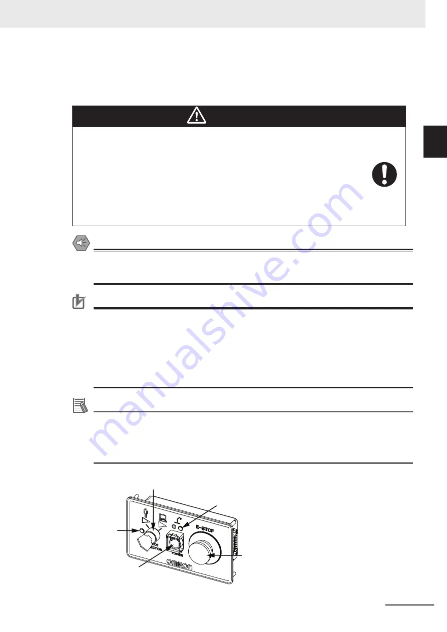
Control Power
LED Indicator
Mode Selection
Switch
High Power
Enable Button
Emergency
Stop Button
High Power
Indicator
1 Overview
1-7
i4H Robots User's Manual (I660)
1-2
Robot Features
1
1-2-4
Front Panel
Summary of Contents for i4-650H
Page 1: ...i4H Robots User s Manual i4 650H i4 750H i4 850H I660 E 02...
Page 6: ...Manual Information 4 i4H Robots User s Manual I660...
Page 74: ...2 Specifications 2 20 i4H Robots User s Manual I660...
Page 142: ...5 Troubleshooting 5 6 i4H Robots User s Manual I660...
Page 176: ...Appendix A 16 i4H Robots User s Manual I660...
Page 177: ...I Index I 1 i4H Robots User s Manual I660 I...
Page 180: ...Index I 4 i4H Robots User s Manual I660...
Page 181: ......


