37
Editing Unit Parameters
Section 5-1
(5) When connecting to a combination of a W-series Servo Drive and the
JUSP-NS115, to a W-series Servo Drive with built-in communications, to
a SMARSTEP Junior Servo Drive (with built-in communications), to a G-
series Servo Drive (with built-in communications), or to a G5-series Servo
Drive (with built-in communications), set the transfer cycle to 4 ms or less.
Automatic
Communications
Setting
By clicking the
Auto Communications Setting
Button, the Communications
and Transfer Cycles corresponding to the largest axis No. registered in the
Position Control Unit are set to their minimum values.
For details on the values of the Communications Parameters set in Automatic
Communications Setting, refer to
6-2-3 MECHATROLINK Communications
Settings
in the
CS1W-NCF71/CJ1W-NCF71 Position Control Units Operation
Manual
(Cat. No. W426).
5-1-3
Editing Axis Parameters
Edit Axis Parameter Window
1,2,3...
1.
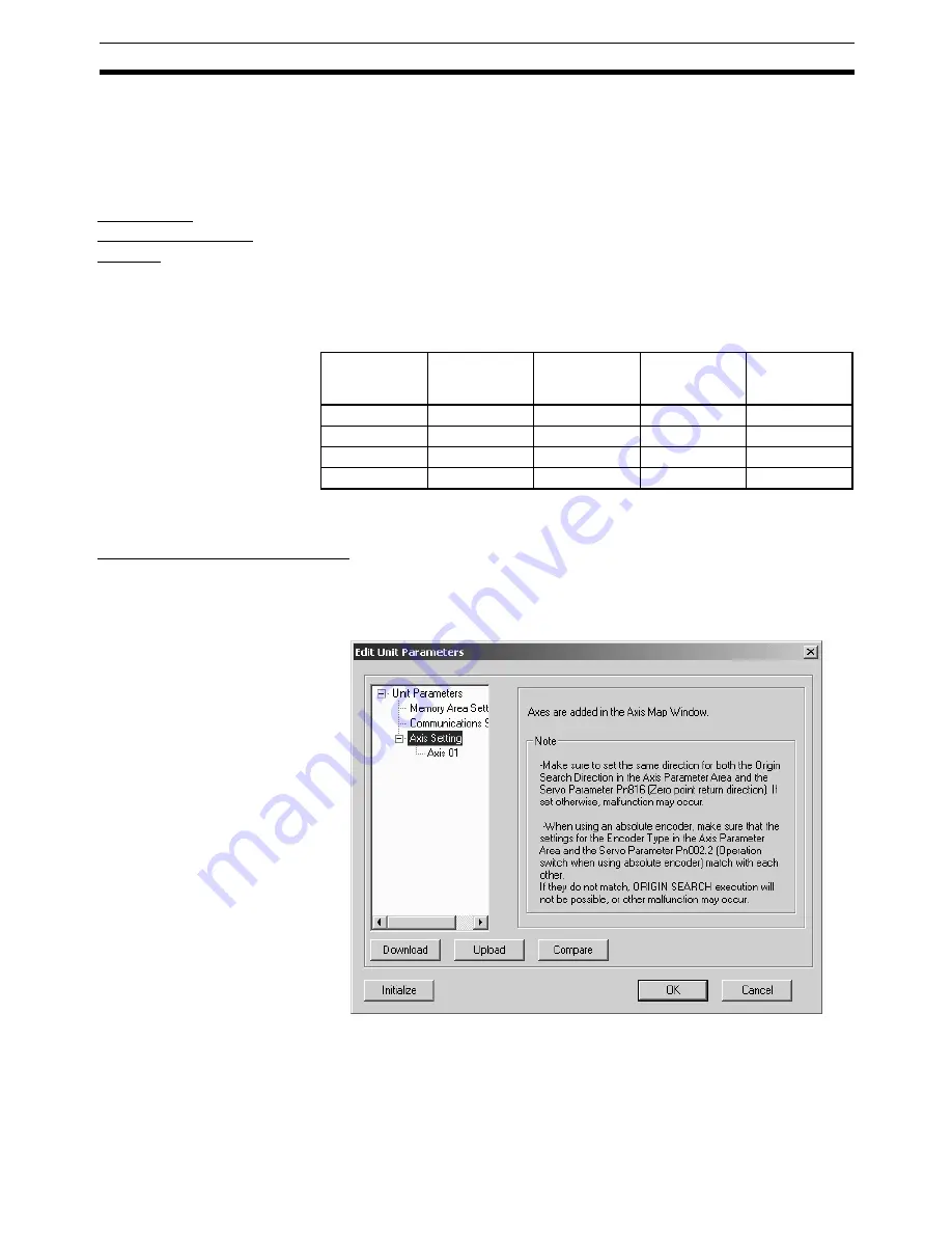
To edit Axis Parameters, click the
Plus
Icon left of the Axis Setting in the
tree in the Edit Unit Parameter Window at first. The registered axes will be
displayed.
Note
When no axes are registered, the Axis Parameters cannot be edited in the
Edit Unit Parameter Window. Register axes in the Axis Map Setting Window
first and edit the Axis Parameters. Once axes are registered in the Axis Map
Setting Window, they will be automatically displayed in the Edit Unit Parame-
ter Window.
Largest axis
No.
Transfer Cycle
Communica-
tions Cycle
No. of Com-
munications
Retries
C2 Master
Connection
1 to 4
1.0 ms
×
1 (1.0 ms)
1
No C2 Master
5 to 8
1.0 ms
×
2 (2.0 ms)
1
No C2 Master
9 to 10
2.0 ms
×
1 (2.0 ms)
1
No C2 Master
11 to 16
2.0 ms
×
2 (4.0 ms)
1
No C2 Master
Summary of Contents for CX-MOTION-NCF - V1.9
Page 1: ...Cat No W436 E1 09 CX Motion NCF Ver 1 9 SYSMAC CXONE AL_C V3 CXONE AL_D V3 OPERATION MANUAL...
Page 2: ......
Page 3: ...CXONE AL C V3 CXONE AL D V3 CX Motion NCF Ver 1 9 Operation Manual Revised September 2009...
Page 4: ...iv...
Page 6: ...vi...
Page 20: ...xx...
Page 24: ...xxiv Application Precautions 5...
Page 36: ...12 Connecting to PLC Section 2 2...
Page 40: ...16 Screen Name Section 3 1 Monitor Windows Axis Monitor Window Unit Monitor Window...
Page 66: ...42 Editing Servo Parameters Section 5 2...
Page 71: ...47 Print Section 6 5 Print Samples An example of printed Unit Parameters is shown below...
Page 92: ...68 Writing to Flash Memory Section 7 6...
Page 106: ...82 Axis Monitor Section 8 2...
Page 112: ...88 Test Run Section 9 1...
Page 138: ...114 Troubleshooting Section 11 3...
Page 142: ...118 Index...
Page 146: ...122 Revision History...


