36
Editing Unit Parameters
Section 5-1
5-1-2
Editing Communications Parameters
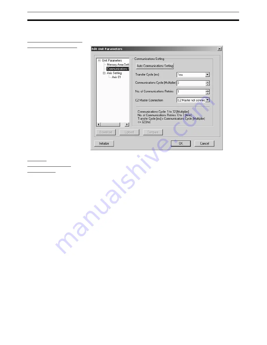
Edit Communications
Parameters Window
Select
Communications Setting
from the tree.
Editing
Communications
Parameters
For details of the communications settings, refer to SECTION 6 MECHA-
TROLINK in the
CS1W-NCF71/CJ1W-NCF71
Position Control Units
Opera-
tion Manual
(Cat. No. W426).
1,2,3...
1.
Set Transfer Cycle.
Click the drop-down list of the Transfer Cycle and select an appropriate
Transfer Cycle.
2.
Set Communications Cycle.
The setting range is between 1 and 32. The set value is used as the mul-
tiplier with which the Transfer Cycle is multiplied. When a value out of the
setting range is entered, the value will be displayed in red. Enter a value
within the range.
3.
Set No. of Communications Retries.
The setting range is between 0 to 7. When a value out of the setting range
is entered, the value will be displayed in red. Enter a value within the range.
4.
Set C2 Master Connection.
Click the drop-down list of the C2 Master Connection and select whether
the C2 Master is connected or not.
Note
(1) Set the Communications and Transfer Cycles so that the following ex-
pression is satisfied: Transfer Cycle
×
Communications Cycle (Multiplier)
≤
32 ms
(2) When connecting to a combination of a W-series Servo Drive and the
JUSP-NS115, set the communications cycle to an integer multiple of
1.0 ms.
(3) When connecting to a W-series Servo Drive with Built-in Communica-
tions, set the communications cycle to an integer multiple of 0.5 ms.
(4) When connecting to a SMARTSTEP Junior with Built-in Communications,
set the transfer cycle to 1.0 ms or more.
Summary of Contents for CX-MOTION-NCF - V1.9
Page 1: ...Cat No W436 E1 09 CX Motion NCF Ver 1 9 SYSMAC CXONE AL_C V3 CXONE AL_D V3 OPERATION MANUAL...
Page 2: ......
Page 3: ...CXONE AL C V3 CXONE AL D V3 CX Motion NCF Ver 1 9 Operation Manual Revised September 2009...
Page 4: ...iv...
Page 6: ...vi...
Page 20: ...xx...
Page 24: ...xxiv Application Precautions 5...
Page 36: ...12 Connecting to PLC Section 2 2...
Page 40: ...16 Screen Name Section 3 1 Monitor Windows Axis Monitor Window Unit Monitor Window...
Page 66: ...42 Editing Servo Parameters Section 5 2...
Page 71: ...47 Print Section 6 5 Print Samples An example of printed Unit Parameters is shown below...
Page 92: ...68 Writing to Flash Memory Section 7 6...
Page 106: ...82 Axis Monitor Section 8 2...
Page 112: ...88 Test Run Section 9 1...
Page 138: ...114 Troubleshooting Section 11 3...
Page 142: ...118 Index...
Page 146: ...122 Revision History...


