


C–12
XR-56-201 5
Applications 03/18
Applications
SNMP also helps avoid conflicting actions being carried out where several engineers have access to
the same test results through the concepts of a Public Community with read access to machines on
the network and a Private Community with write access to one or more machines. In both cases, this
access is under password control but with the default values of
public
for the read access and
private
for write access. Changing either of these passwords on a particular machine will limit access to users
who give the correct password.
Set-up
Four actions are required when setting up one or more Ultra for automated control.
1. Linking the Ultra(s) in a single LAN, together with the device from which the systems are
monitored.
2. Giving each Ultra a unique name and location to allow easy identification.
3. Programming the device from which the systems are to be monitored with the appropriate
SNMP Manager application.
4. Uploading a copy of the Omnitek Ultra MIB to the SNMP manager.
Linking the boxes into a single LAN
Typically either the device from which the automated control is to be driven need to be added to the
network that the Ultra is already on or the Ultra needs to be added to a network that includes the
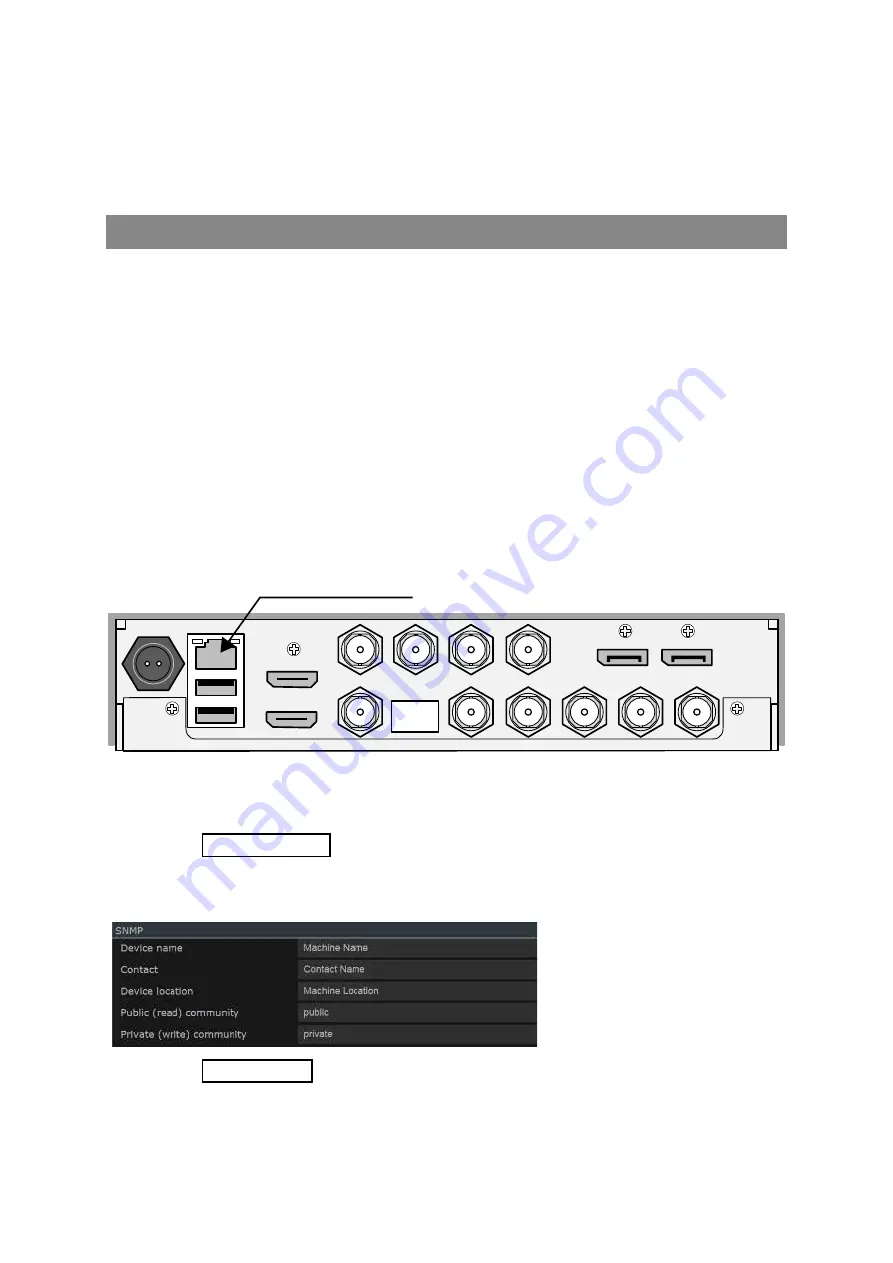
device from which it will be remotely controlled. The Ultra must be connected to the LAN using the
network connection:
Output
Input
SDI 1
AUX 1
AUX 2
AUX 3
AUX 4
Sync / CVBS
USB
Input
Output
SDI 2
SDI 3
SDI 4
Eye
HDMI
Input
Output
DisplayPort
LAN Connection (Ethernet)
Use a suitable cable to physically connect each Ultra to the same network router and Link the control
device into the same network.
See the "Network Section" section of the Configuration chapter for details how to set up the
units IP Address.
Giving each Ultra a unique name and location
The name and location for any
Ultra system are set in the SNMP
section of the “Configuration” -
“System” menu.
See the "SNMP Section" section of the Configuration chapter for details
Simply set whatever details you require as the
Device Name
and the
Device Location
, replacing the
Machine Name
and
Machine Location
details shown in the image.
Summary of Contents for Ultra XR
Page 13: ...Ultra XR User Guide 1 1 XR 56 201 5 1 Overview...
Page 14: ...1 2 XR 56 201 5 Overview 03 18 Overview...
Page 16: ...1 4 XR 56 201 5 Overview 03 18 Overview...
Page 25: ...Ultra XR User Guide 2 1 XR 56 201 5 2 Viewer...
Page 26: ...2 2 XR 56 201 5 Viewer 03 18 Viewer...
Page 38: ...2 14 XR 56 201 5 Viewer 03 18 Viewer...
Page 56: ...2 32 XR 56 201 5 Viewer 03 18 Viewer...
Page 64: ...2 40 XR 56 201 5 Viewer 03 18 Viewer...
Page 76: ...2 52 XR 56 201 5 Viewer 03 18 Viewer...
Page 80: ...2 56 XR 56 201 5 Viewer 03 18 Viewer...
Page 85: ...Ultra XR User Guide 3 1 XR 56 201 5 3 Generator...
Page 86: ...3 2 XR 56 201 5 Generator 03 18 Generator...
Page 92: ...3 8 XR 56 201 5 Generator 03 18 Generator...
Page 93: ...Ultra XR User Guide 4 1 XR 56 201 5 4 Configuration...
Page 94: ...4 2 XR 56 201 5 Configuration 03 18 Configuration...
Page 108: ...4 16 XR 56 201 5 Configuration 03 18 Configuration...
Page 120: ...4 28 XR 56 201 5 Configuration 03 18 Configuration...
Page 121: ...Ultra XR User Guide 5 1 XR 56 201 5 5 Connections...
Page 122: ...5 2 XR 56 201 5 Connections 03 18 Connections...
Page 141: ...Ultra XR User Guide A 1 XR 56 201 5 A Glossary...
Page 142: ...A 2 XR 56 201 5 Glossary 03 18 Glossary...
Page 150: ...A 10 XR 56 201 5 Glossary 03 18 Glossary...
Page 151: ...Ultra XR User Guide B 1 XR 56 201 5 B Installation...
Page 152: ...B 2 XR 56 201 5 Installation 03 18 Installation...
Page 158: ...B 8 XR 56 201 5 Installation 03 18 Installation...
Page 162: ...B 12 XR 56 201 5 Installation 03 18 Installation...
Page 169: ...Ultra XR User Guide C 1 XR 56 201 5 Ultra XR User Guide C 1 XR 56 201 5 C Applications...
Page 170: ...C 2 XR 56 201 5 Applications 03 18 Applications...
Page 176: ...C 8 XR 56 201 5 Applications 03 18 Applications...
Page 184: ...C 16 XR 56 201 5 Applications 03 18 Applications...


