


------------------------------------- Generator: Basics --------------------------------------
Ultra v2.0a User Guide
V-3
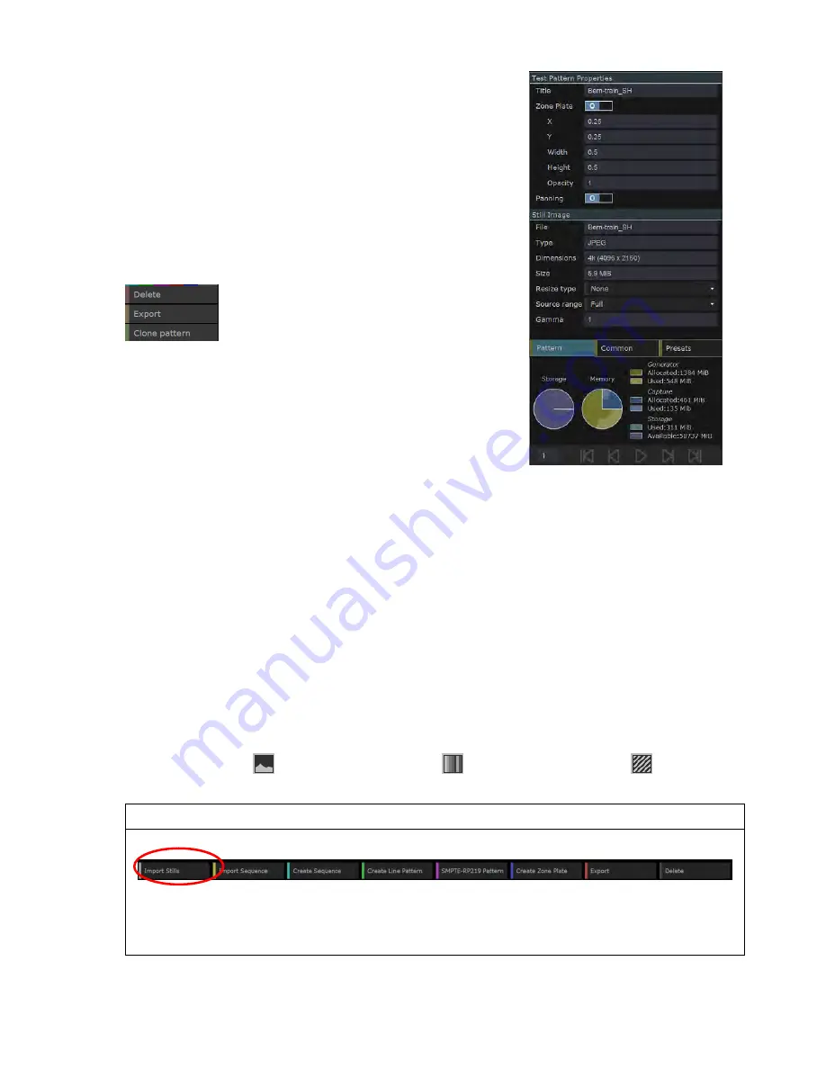
Right-Hand Panel
The right-hand panel of the Generator window offers three pages
of further control. The Patterns page shows details of the test
pattern currently selected by the cursor and how it is configured
to be played out: it also allows this configuration to be changed
(see Section X). The Common page is concerned with driving the
Ultra
’s Playlist feature. The Presets page is concerned with
recording and recalling sets of test pattern data.
Right-Click Menu
Right-clicking on any test pattern calls up a
context-sensitive menu, typically offering the
option to
Delete
,
Export
or
Clone
the selected
pattern(s).
Note:
These options affect all the test patterns that are currently
highlighted so before taking either of these options, check that
you have only highlighted the test patterns you want to affect.
V.2 Test Patterns from Still Images
This section describes the use of still images as test patterns. The steps required to use sequences of
such images as test patterns are slightly different and are described in Section V.3.
V.2.1 Importing Still Images
Use the following steps to create a test pattern from:
Video stills – stored as JPEG, BMP, RAW, DPX, YUV, SGI, TIFF or RVF files.
The same steps can also be used to import:
Line patterns stored in Omnitek’s proprietary LPD format (see Section W.1)
Zone plates stored on disk in Omnitek’s proprietary ZPD format (see Section W.2), and
Test patterns that have been exported as an .oaf file (see Section W.4)
The type of image that is the source of the test pattern is indicated by an icon in the bottom right-
hand corner of the thumbnail – as follows:
Still Image
Line Pattern
Zone Plate
To import a still image for use as a test pattern:
1.
Click on the
Import
Stills
option in the Button Bar at the bottom of the screen.
2.
Use the file selection dialogue that is displayed to pick out the required file.
After checking the image file and saving it to flash on the
Ultra
, a thumbnail for the image is then
added to the display. The new test pattern also automatically starts being played out (see below).
Summary of Contents for Ultra 4K Tool Box
Page 1: ...Ultra 4K Tool Box User Guide Version 2 0a August 2015...
Page 8: ...General Ultra v2 0a User Guide...
Page 50: ...General Automated Control Ultra v2 0a User Guide C 6...
Page 52: ...Conversion Facilities Ultra v2 0a User Guide...
Page 62: ...Signal Analysis Ultra v2 0a User Guide...
Page 96: ...Signal Analysis Status Ultra v2 0a User Guide O 4...
Page 98: ...Physical Layer Analysis Ultra v2 0a User Guide...
Page 112: ...Physical Layer Eye Jitter Ultra v2 0a User Guide S 14...
Page 118: ...Generator Ultra v2 0a User Guide...
Page 134: ...Generator Creating Test Patterns W 8 Ultra v2 0a User Guide...
Page 139: ...Ultra v2 0a User Guide...


