


------------------------------- Physical Layer: Eye & Jitter --------------------------------
Ultra v2.0a User Guide
S-7
S.3 Jitter
The
Ultra
presents four Views of the jitter content within the carrier signal:
Jitter Meters (see Section S.3.2)
Jitter Spectrum (see Section S.3.3), and
Jitter Histogram (see Section S.3.4)
Jitter Waveform (see Section S.3.5)
S.3.1 Selecting Jitter displays
The various Jitter displays can all be called up on the Viewer window as follows:
To display any of the Jitter displays:
In the Viewer window:
1.
Click on the down-arrow in the Title Bar of the tile that you want to replace.
2.
Select the required
Jitter
xxx
option from the menu that is displayed.
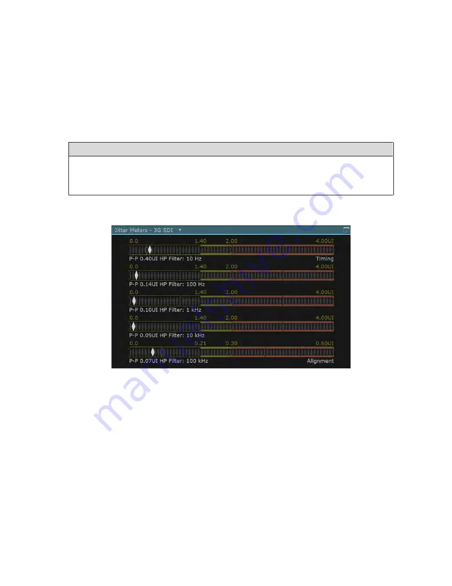
S.3.2 Jitter Meters
Figure S-8:
Jitter Meters display
The Jitter Meters display comprises a set of ‘traffic light’-coloured meters, each including a
diamond-shaped solid marker that indicates (in a suitably dampened way) the effect of jitter in the
selected pass band on the position of the clock edges in the carrier signal that is being analysed.
Alongside each solid marker is an ‘open’ marker that shows the current instantaneous jitter value.
The upper bound of the pass band in each case is about 5MHz, the lower bound is set by the high
pass filter that is applied. This is detailed below the meter, along with the measured peak-to-peak
(P-P) value. The meters that show Timing Jitter and Alignment Jitter for the video standard that is
being analysed are indicated on the display.
Comparing the readings of the different meters allows you to deduce the waveband(s) in which
jitter energy is chiefly concentrated. Identifying these wavebands often provides a clue to the
source of the jitter.
Each meter is divided into a clear section (in which the markers are white), an amber section in
which the markers are yellow and a red section in which the markers are also red. A red marker
corresponds to a jitter level that is over the error level specified on the Video page of the
Configuration window. A yellow marker corresponds to a jitter level that is between 70% and
Summary of Contents for Ultra 4K Tool Box
Page 1: ...Ultra 4K Tool Box User Guide Version 2 0a August 2015...
Page 8: ...General Ultra v2 0a User Guide...
Page 50: ...General Automated Control Ultra v2 0a User Guide C 6...
Page 52: ...Conversion Facilities Ultra v2 0a User Guide...
Page 62: ...Signal Analysis Ultra v2 0a User Guide...
Page 96: ...Signal Analysis Status Ultra v2 0a User Guide O 4...
Page 98: ...Physical Layer Analysis Ultra v2 0a User Guide...
Page 112: ...Physical Layer Eye Jitter Ultra v2 0a User Guide S 14...
Page 118: ...Generator Ultra v2 0a User Guide...
Page 134: ...Generator Creating Test Patterns W 8 Ultra v2 0a User Guide...
Page 139: ...Ultra v2 0a User Guide...


