


Field Service Ver. 1.0 Jun. 2008
10. Service Mode
247
Adjustment / Setting
Mode
Default value
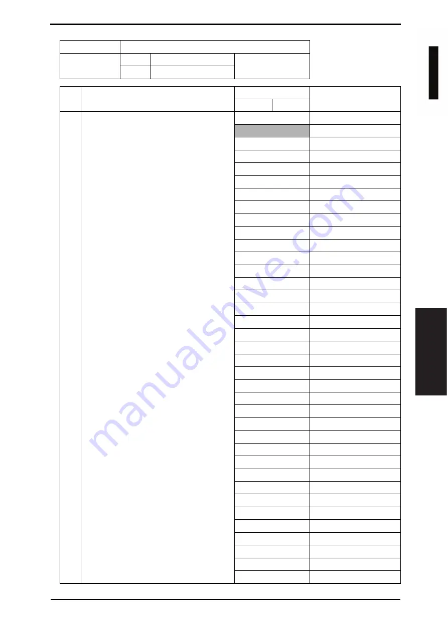
821
Bit
7654 3210
HEX: 04
State
0000 0100
Bit
Setting item
Setting value
Description
0
1
7-2
Language code (for input/output)
• Sets the language for import/export.
• Internet fax, IP address fax, SIP-FAX and
IP relay are switched with this language.
This language code is also used for send-
ing the file for communication administra-
tion data.
000000
Japanese
000001
English
000010
German
000011
French
000100
Italian
000101
Spanish
000110
Chinese (simplified)
000111
Korean
001000
Taiwanese (Cantonese)
001001
Dutch
001010
Portuguese
001011
Danish
001100
Norwegian
001101
Swedish
001110
Finnish
001111
Arabic
010000
Not available
010001
Ukrainian
010010
Estonian
010011
Greek
010100
Croatian
010101
Slovakian
010110
Thai
010111
Czech
011000
Turkish
011001
Hungarian
011010
Polish
011011
Not available
011100
Latvian
011101
Lithuanian
011110
Romanian
011111
Russian
100000
Slovene
100001
Persian
100010
Hebrew
100011
(Reserved)
others
Not available
d
-Color
M
F
201
Y109660-1 Sevice Manual


