10. Service Mode
Field Service Ver. 1.0 Jun. 2008
152
Adjustment / Setting
10.3.3
Printer Area
A. Leading Edge Adjustment
Functions
• To change and adjust the position to start printing in sub scan direction per paper
type or per front or back page on the tray 1.
(To adjust the timing where paper is sent out from the timing roller)
Use
• The PH unit has been replaced.
• The paper type has been changed.
• The image on the copy deviates in the sub scan direction.
• A faint image occurs on the leading edge of the image.
• This setting can be made independently for plain paper, thick 1, thick 2, thick 3, OHP
film, and envelopes.
Adjustment
Specification
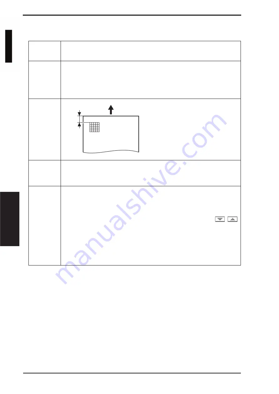
Width A on the test pattern produced should
fall within the following range.
Specifications: 4.2
r
0.5 mm
Setting range: -3.0 mm to +3.0 mm
(in 0.2 mm increments)
Adjustment
Instructions
If width A is longer than the specifications, make the setting value smaller than the cur-
rent one.
If width A is shorter than the specifications, make the setting value greater than the cur-
rent one.
Setting/
Procedure
1.
Place A3 or 11 x 17 paper on the tray1.
2.
Call the Service Mode to the screen.
3.
Touch [Machine Adjustment]
o
[Printer Area]
o
[Leading Edge Adjustment].
4.
Press the Start key to let the machine produce a test pattern.
5.
Check the dimension of width A on the test pattern.
6.
If width A falls outside the specified range, change the setting using the
/
keys.
7.
Press the Start key to let the machine produce a test pattern.
8.
Check the dimension of width A on the test pattern.
9.
If width A is outside the specified range, change the setting again and make a check
again.
10.
If width A falls within the specified range, touch [OK].
11.
Following the same procedure, adjust for thick 1 to 3, OHP film, and envelope.
A00JF3C504DA
Width A
d-Color MF201
Service Manual Y109660-1


