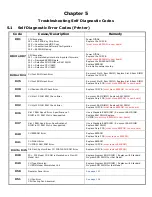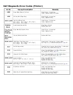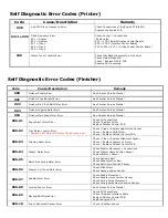
Self Diagnostic Error Codes (Printer)
Code
Cause/Description
Remedy
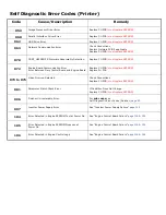
167 to 169
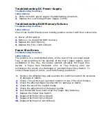
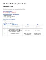
167 = Thermistor Slope error
168 = Compensation Thermistor Error
169 = Upper Side Thermistor Error
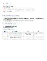
See “Fuser Failure”
page 99
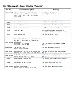
170 to 176
Fuser thermistor Short Circuit / Open Circuit
High Temperature / Low Temperature
See “Fuser Failure”
page 99
179
Wrong Fuser Installed
Install Correct Fuser / Replace The Fuser
See “Fuser Mismatch Error”
page 112
180 to 186
Communication Error
180 = Envelope Feeder 181 = Duplex 182 = 2
nd
Tray
183 = 3
rd
Tray 184 = 4
th
Tray 185 = 5
th
Tray
186 = Finisher
Install Option / Check Connections
Replace Engine Control PCB
See “Tray 1, 2, 3, 4 Communication Errors”
page 108
187
Communication with Control Panel Error
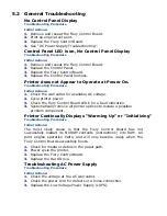
See “General Troubleshooting”
page 97
and
“ Control Panel Communication Failure”
page 120
188
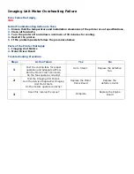
Sub CPU I/F Error
Check Connection of the Motor Driver Board.
Replace the Motor Driver Board / Engine Control Board
189
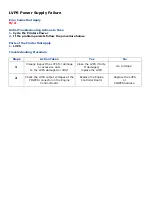
Inverter Unit I/F Error
See
“Inverter Unit Interface Failure”
page 109
190
System Memory Overflow
Replace CU PCB
(must replace EEPROM)
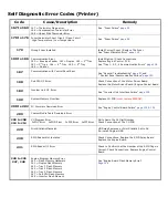
200 to 202
PU Firmware Download Error
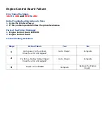
See “Engine Control Board Failure”
page 102 & 124
209
Custom Media Table Download Error
203 to 208
210 to 214
CU Program Error
0xFOC Error 0xFOD Error 0xFFE Error 0xFFF Error
Write Down the 24 Digit Number
Check Connection of the CU PCB
220
Print Statistic Mismatch
HDD was Removed or Print Statistic Set to On
Re-install Original HDD
230
RFID Reader Not Installed
Check Connections. Replace the RFID Relay Board
Replace the Engine Board.
231
RFID Reader I/F Error
Check to Confirm that the Number of the RFID Tags is
Correct. Check Connections. Replace Engine Control
Board.
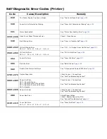
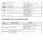
240 to 245
247, 248
Engine Program Memory Error
240 = Flash Memory Hardware
241 = Duplex Flash Memory
243 = Tray 3 Flash Memory
244 = Tray 4 Flash Memory
245 = Tray 5 Flash Memory
247 = Sub CPU Flash Memory
248 = Inverter Flash Memory
See “Engine Board Flash Memory Error”
Page 124
Summary of Contents for C9800 Series
Page 30: ...Step 3 Setting up the ES 1000 Spectrophotometer...
Page 31: ...Once installation is complete re launch Command Workstation...
Page 32: ......
Page 33: ......
Page 34: ......
Page 35: ......
Page 36: ......
Page 37: ......
Page 38: ......
Page 39: ......
Page 40: ......
Page 41: ......
Page 42: ......
Page 43: ......
Page 44: ......
Page 45: ......
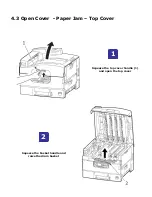
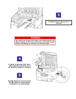
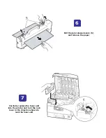
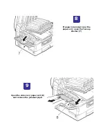
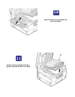
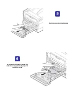
Page 77: ...Close the side cover Carefully remove the jammed paper 4 3...
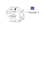
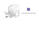
Page 83: ...Close the top cover and ensure that it is latched 12...
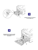
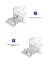
Page 87: ...Raise the front cover of the duplex unit Replace the two top covers 8 7...

