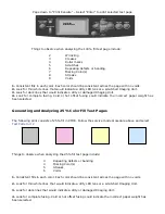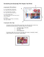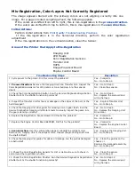
Mis-Registration, Color Layers Not Correctly Registered
The image appears blurred and the primary colors are not aligning correctly into one
image. For a page oriented Long-Edge Feed, the following applies:
If the colors are shifted from left to right, this is mis-registration in the
process direction
.
If the colors are shifted from top to bottom, this is mis-registration in the
scan direction
.
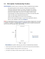
Initial Actions:
Perform Initial Actions from
Print Quality Troubleshooting Practices
If the mis-registration is in the horizontal direction, perform the color registration
adjustment
If the mis-registration is in the vertical direction, clean the Sensor.
Areas of the Printer that Apply to Mis-Registration
Imaging Unit
LED Heads
Color Registration Sensors
Transfer Unit
HVPS
Image Processor Board
Engine Control Board
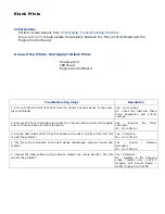
Troubleshooting Steps
Resolution
1. Cycle power to the printer. Did this correct the problem?
Yes – Complete
No - Go to Step 2.
2.
Process Direction:
Remove the Imaging Units and
Transfer Unit. Inspect the
Color
Registration Sensors for dirt, debris
or toner build-up.
Are the sensors
clean?
Yes – Go to Step 3.
No - Clean the sensors.
3. Check the Color Registration Shutter. Run the Service Diagnostics Registration
Shutter test. Is the shutter functioning correctly?
Yes – Go to Step 4.
No - Replace the solenoid and
wiring harness.
4. Inspect the Transfer Unit for tears or damage on the edges of the belt. Is the
belt damaged?
Yes – Replace Transfer Unit.
No - Go to Step 5.
5. Check the Imaging Unit drive gears for missing or worn gear teeth. Run the
Service Diagnostics Imaging Unit Motors tests to visually inspect the gears. Are
the gears working correctly?
Yes – Go to Step 6.
No - Replace the Imaging Unit
Drive Gear.
6. Replace the Registration Sensor Board. Did this fix the problem?
Yes – Complete.
No - Go to Step 8.
7. Replace the Engine Control Board EEPROM. Did this fix the problem?
Yes – Complete.
No - Replace the Engine Control
Board
8.
Scan Direction:
Use the configuration page to identify the
problem color.
Remove the Imaging Unit of the
suspect color. Inspect the grounding
shaft.
Has
the shaft shifted?
Yes – Replace the Imaging Unit.
No - Go to Step 9.
9. Check the Imaging Unit guides for debris or damage. Are the guides damaged
or obstructed?
Yes – Clean the guides on the
chassis or
Replace the damaged assembly.
No - Go to Step 10.
10. Check the Color Registration Sensors for dirt or debris. Be sure to check in
and around the registration shutter.
Yes – Clean the sensor.
No - Go to Step 11.
11. Check the Color Registration Shutter. Run the Service Diagnostics Registration
Shutter test. Is the shutter functioning correctly?
Yes – Go to Step 12.
No - Replace the solenoid and
wiring harness.
Summary of Contents for C9800 Series
Page 30: ...Step 3 Setting up the ES 1000 Spectrophotometer...
Page 31: ...Once installation is complete re launch Command Workstation...
Page 32: ......
Page 33: ......
Page 34: ......
Page 35: ......
Page 36: ......
Page 37: ......
Page 38: ......
Page 39: ......
Page 40: ......
Page 41: ......
Page 42: ......
Page 43: ......
Page 44: ......
Page 45: ......
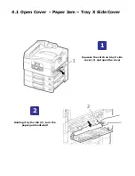
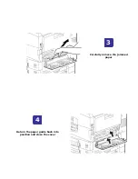
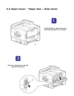
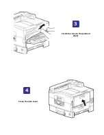
Page 77: ...Close the side cover Carefully remove the jammed paper 4 3...
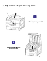
Page 83: ...Close the top cover and ensure that it is latched 12...
Page 87: ...Raise the front cover of the duplex unit Replace the two top covers 8 7...

