99
Roll Media Option Hardware
media drive. This system accurately advances the roll of media during printing. The
roll media is positioned accurately with a high resolution media encoder as it moves
past the carriage printheads. This ensures accurate and high quality prints on various
core media.
[32]
[32] Roll Media Hardware
(1 – 3)
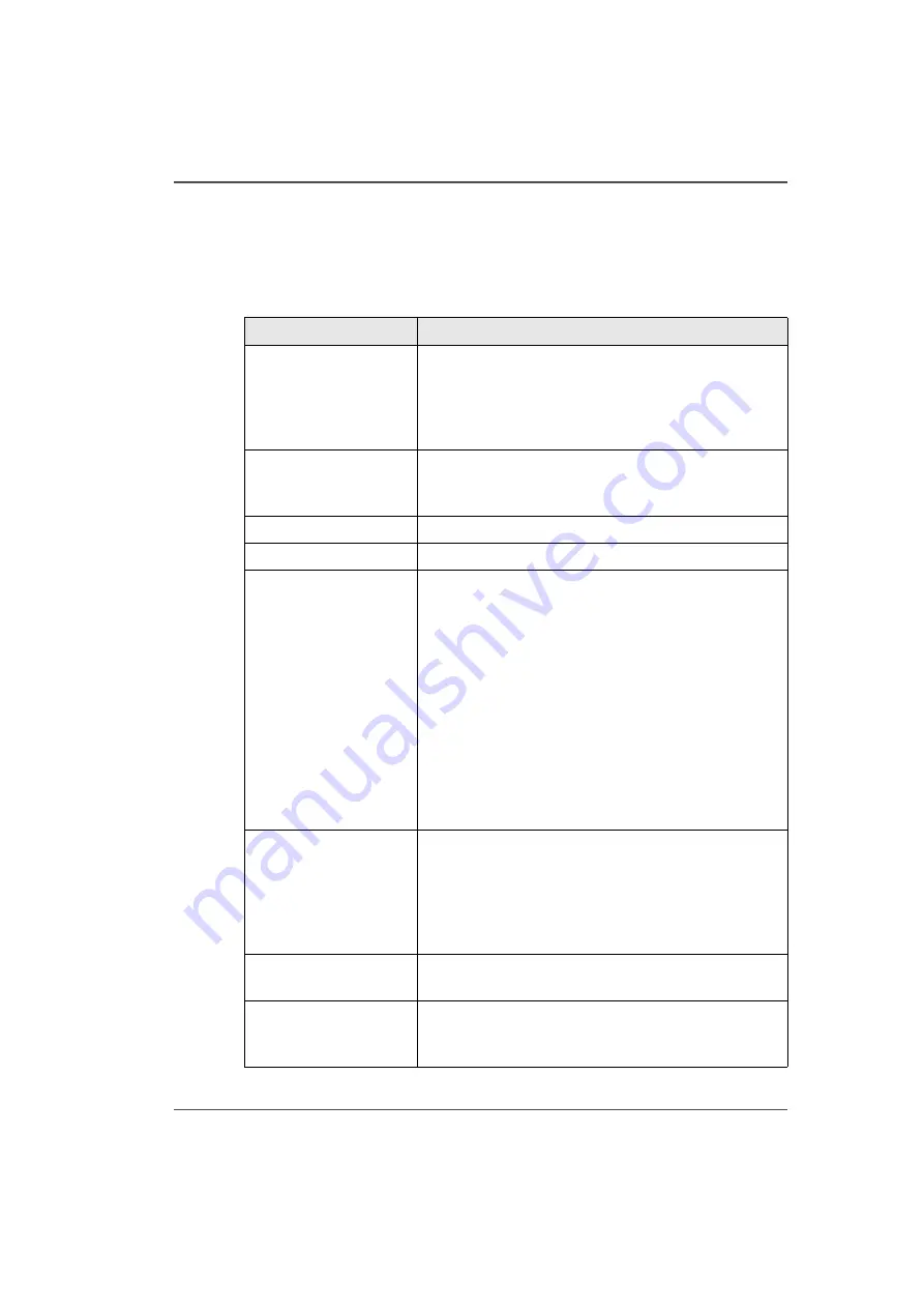
Component
Function
1) Dual Foot Pedal
Switch
The dual foot pedal switch is tethered to the printer by
a cable and located on the floor under the RMO unit. It
is used to control media feed in both forward and
reverse directions. Function varies depending on
whether media is loaded or unloaded.
2) Media Drive Couplers The couplers keep the media shafts in place and
engaged to the drive motor. In the open (horizontal)
position they allow the media shafts to be removed.
3) Supply Shaft Motor
Drives the supply media shaft.
4) Take-up Shaft Motor
Drives the take-up media shaft.
5) Media Shafts
The shafts hold the roll media core in place. This can be
an empty core or a core with a roll of media, depending
on whether the shaft is used for take-up or supply. The
media shaft consists of a ribbed aluminum extrusion
with a spring-loaded spike assembly inside it. There is
a large track roller at each end, and a drive motor at one
end. The media shaft is designed to slide inside a roll of
media with a 3" cardboard core. It uses spring-loaded
core locks to lock the roll of media to the media shaft.
The locks can be engaged or released using a hex key.
The media shaft supports the media roll, provides
aligned positioning of the media roll in the printer, and
transfers driving torque to the media roll.
6) Media Access Door
Opens to provide access to the roll of media to allow
media loading. Also eliminates a possible shear hazard
to the operator between the carriage and the roll unit
endplates. The door has a safety interlock switch. If the
door is open no carriage or gantry motion can be
initiated at the printer.
7) Cutting Guide
A gutter between two pieces of sheet metal that guides
a blade to cut the media.
8) Media Core Locks
Hold the media core in place on the media shafts. Use
the supplied hex key to lock and unlock the media core
at the right end of the media shaft.
Summary of Contents for Arizona 250 GT
Page 1: ...Arizona 250 GT Oc User manual User Manual Revision D...
Page 6: ...6 Table of Contents...
Page 7: ...7 Chapter 1 Introduction...
Page 16: ...16 Chapter 1 Introduction Product Compliance...
Page 17: ...17 Chapter 2 Product Overview...
Page 21: ...21 Chapter 3 Safety Information...
Page 45: ...45 Chapter 4 How to Navigate the User Interface...
Page 51: ...51 Operator Interface Hardware Thermal fluid heater Purge pump Purge valve Printheads jetting...
Page 70: ...70 Chapter 4 How to Navigate the User Interface Installation and Upgrade Module...
Page 71: ...71 Chapter 5 How to Operate the Arizona 250 GT...
Page 96: ...96 Chapter 5 How to Operate the Arizona 250 GT Underlay Board to Reduce Artifacts...
Page 97: ...97 Chapter 6 How to Operate the Roll Media Option...
Page 122: ...122 Chapter 6 How to Operate the Roll Media Option How to Determine Media Advance Correction...
Page 123: ...123 Chapter 7 How to Use the Static Suppression Upgrade Kit...
Page 127: ...127 Chapter 8 Ink System Management...
Page 134: ...134 Chapter 8 Ink System Management How to Change Ink Bags...
Page 135: ...135 Chapter 9 Error Handling and Troubleshooting...
Page 139: ...139 Chapter 10 Printer Maintenance...
Page 172: ...172 Chapter 10 Printer Maintenance How to Clean the Rubber Capstan...
Page 173: ...173 Appendix A Application Information...
Page 176: ...176 Appendix A Application Information Application Resources on the Web Site...


