54
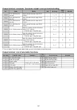
Constants for output terminal C1
~
C4
Pn120
C1 Output function selection
Pn121
C2 Output function selection
Pn122
C3 Output function selection
Pn123
C4 Output function selection
Each function of the output terminal (C1-E1
~
C4-E4) is set by selecting the output function (Pn120
~
Pn123).
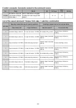
The relationship between set value and its corresponding function is as follows:
Set value
1 Error detection signal
Turn off if an error is detected.
2 Brake timing signal
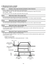
The timing signal will output for mechanical brake ON/OFF.
3 Rotation pulse
4 CW pulse
5 CCW pulse
6 Rotation direction signal
Output the signal (pulse) depending on the motor rotation.
The number of pulses is 18 pulses per rotation.
Output signal for each setting is shown in the following diagram.
Rotation direction
* For pulse waveform
* Duty ratio variable
Specified torque over
Rotation direction signal
CW pulse
CCW pulse
The output signal will turn on by supplying the power source again or setting the free-run stop/error reset input.
* For more information, see the description of the mechanical brake-related parameters Pn220 to Pn224.
Specification of the output pulse will be shown in the diagram on
the right. Select the counter according to the specifications.
13
7
Rotation pulse
CW pulse
CCW pulse
6
Signal during operations
Remarks
1
8
Signal during rotations
3
Set only for Pn122
and Pn123. (C3-
E3, C4 - E4
terminal)
10
4
11
Specified speed over
Rated torque over
Signal during torque
limit
Rotation pulse
5
12
Speed matching signal
Error detection signal
Brake timing signal
Set value
Remarks
Function name
Function name
2
9
■ Output terminal constant
20 μs
3 μs
500 μs fixed
ON
OFF
CW rotation
CCW rotation
Switch on the first pulse after reversing the rotation direction


