15
[Important] *
Regarding source connection to customers who are using old type drivers,
if the similar old type wiring is used in new drivers, there are chances of driver output
terminal damage or external power supply damage. Conduct wiring with great caution.
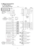
Source connection example
R/L1 and T/L3 are used
for single phase 200 V.
I1 (Multi-function input 1)
I2 (Multi-function input 2)
I3 (Multi-function input 3)
I4 (Multi-function input 4)
I5 (Multi-function input 5)
I6 (Multi-function input 6)
I7 (Multi-function input 7)
I8 (Free-run stop/
Error reset input)
Multi-function
output 1
Multi-function
output 2
Multi-function
output 3
Multi-function
output 4
IC (Input common)
IP (24 V power supply
for external I/F)
0 V (GND for
external I/F)
TB1
TB3
FG
8
9
10
11
19
20
21
22
C1 (OUT1+)
E1 (OUT1-)
C2 (OUT2+)
E2 (OUT2-)
C3 (OUT3+)
E3 (OUT3-)
C4 (OUT4+)
E4 (OUT4-)
5
6
7
CN2
TB3
DC reactor
(optional)
* Remove the shorting
bar when connecting to
a DC reactor.
Three phase
200 V to 240 V
50/60 Hz
R/L1
S/L2
T/L3
FG
FG
18
16
+24 V
17
15
14
13
12
4
3
2
1
TB1
+12 V
+1
+2
U/T1
V/T2
W/T3
FG
B1
B2
FG
External
command setter
10 k
~
20 k
Ω
(Optional)
1
7
3
4
5
2
8
+12 V
+12 V
HU
HV
HW
0V
0 V
Input
noise filter
(optional)
FIL
Cable
extension
(optional)
Regenerative
resistor
(optional)
Operator
Shorting
bar
Cable
extension
(optional)
Pole sensor
Driver
Motor
H (12 V power supply for
external analog)
M (External analog command)
L (GND for external analog)
M


