25
(4)
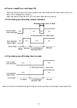
Turn on the switch that is connected in (1), to rotate
the motor in CW direction.
(5)
Turn off the switch that is connected in (1), to stop the
motor.
(3)
-
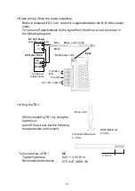
It is a default display when the power supply is turned
on. If the display as shown on the left side appears, it
means wiring is done correctly.
* If nothing is displayed, check the wiring of the power
supply, and start again from (1).
-
As shown on the left, if "bb" blinks, it means that TB1
is not wired correctly.
Try again from (1).
Turn the external command setter to set the rotation
speed.
* The 7 segment LED display as shown on the left
will appear when the speed command is 500 [r/min].
Procedure
No.
Explanatory diagram
Details
(2)
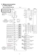
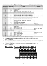
Connect the switch between 0 V (18) and I3 (3) of
TB1 and set the switch to OFF state.
(Connect the switch to the selection of speed
command 1.)
Connect the OP-RV-24B20K of option between the
H (5), M (6), L (7) of TB1.
H (5) - Option (3) terminal,
M (6) - Option (2) terminal,
L (7) - Option (1) terminal
Ensure that the wiring is correct again before
supplying the power.
M L C1 C2 C3 C4
I1 I2 I3 I4 H
6 7 8 9 10 11
1 2 3 4 5
IC 0V E1 E2 E3 E4
I5 I6 I7 I8 IP
17 18 19 20 21 22
12 13 14 15 16
Signal
name
Terminal
No.
Signal
name
Terminal
No.
M L C1 C2 C3 C4
I1 I2 I3 I4 H
6 7 8 9 10 11
1 2 3 4 5
IC 0V E1 E2 E3 E4
I5 I6 I7 I8 IP
17 18 19 20 21 22
12 13 14 15 16
Signal
name
Terminal
No.
Signal
name
Terminal
No.


