14
3. Wiring and connection
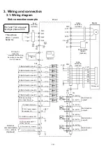
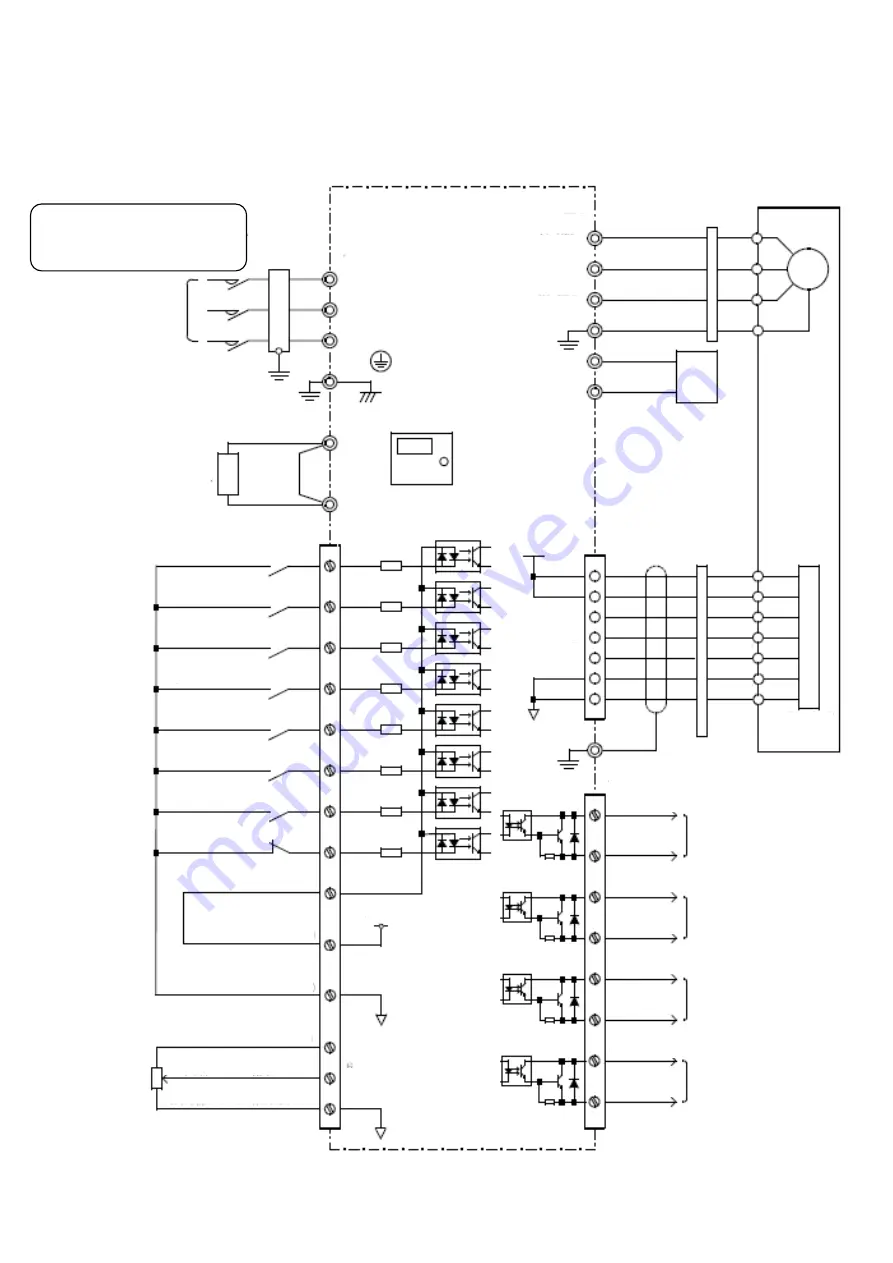
3-1. Wiring diagram
R/L1 and T/L3 are used
for single phase 200 V.
I1 (Multi-function input 1)
I2 (Multi-function input 2)
I3 (Multi-function input 3)
I4 (Multi-function input 4)
I5 (Multi-function input 5)
I6 (Multi-function input 6)
I7 (Multi-function input 7)
I8 (Free-run stop/
Error reset input)
Multi-function
output 1
Multi-function
output 2
Multi-function
output 3
Multi-function
output 4
IC (Input common)
IP (24 V power supply
for external I/F)
0 V (GND for external I/F)
TB1
TB3
FG
8
9
10
11
19
20
21
22
C1 (OUT1+)
E1 (OUT1-)
C2 (OUT2+)
E2 (OUT2-)
C3 (OUT3+)
E3 (OUT3-)
C4 (OUT4+)
E4 (OUT4-)
5
6
7
CN2
TB3
DC reactor
(optional)
* Remove the shorting
bar when connecting
to a DC reactor.
Three phase
200 V
~
240 V
50/60 Hz
R/L1
S/L2
T/L3
FG
FG
H (12 V power supply for
external analog)
18
16
+24 V
17
15
14
13
12
4
3
2
1
TB1
+12 V
+1
+2
U/T1
V/T2
W/T3
FG
B1
B2
FG
External
command setter
10 k
~
20 k
Ω
(Optional)
1
7
3
4
5
2
8
+12 V
+12 V
HU
HV
HW
0 V
0 V
Input
noise filter
(optional)
FIL
Cable
extension
(optional)
Regenerative
resistor
(optional)
Operator
Shorting
bar
Cable
extension
(optional)
Pole sensor
Driver
Motor
Sink connection example
M (External analog command)
L (GND for external analog)
M


