24
Following is the procedure outline:
(1)
Wiring 1
(2)
Wiring 2, Power supply
(3)
Analog speed command
(4)
Starting the CW operation
(5)
Stopping the CW operation
(6)
Digital speed command settings
(7)
Starting the CW operation
(8)
Stopping the CW operation
(1)
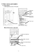
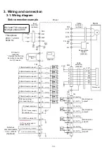
See the interconnection diagram and the terminal
description, to connect the power supply line
and the motor power line to the main circuit terminal.
Also connect the earthing terminal.
* Ensure that the wiring is correct.
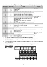
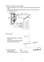
Connect (short-circuit) IP (16) and IC (17) of TB1,
and also connect (short-circuit) 0 V (18) and I8 (15).
Connect the switch between 0 V (18) and I1 (1) of
TB1 and set the switch to OFF state.
(Connect the switch to the CW operation command.)
Procedure
No.
Explanatory diagram
Details
This section describes the procedure for operating the motor by using the
external switch in the initial setting state.
4-2. Starting by using external switch
M L C1 C2 C3 C4
I1 I2 I3 I4 H
6 7 8 9 10 11
1 2 3 4 5
IC 0V E1 E2 E3 E4
I5 I6 I7 I8 IP
17 18 19 20 21 22
12 13 14 15 16
Signal
name
Terminal
No.
Signal
name
Terminal
No.
M L C1 C2 C3 C4
I1 I2 I3 I4 H
6 7 8 9 10 11
1 2 3 4 5
IC 0V E1 E2 E3 E4
I5 I6 I7 I8 IP
17 18 19 20 21 22
12 13 14 15 16
Signal
name
Terminal
No.
Signal
name
Terminal
No.

